Fully-hydraulic reverse braking clutch system
A reverse braking, full hydraulic technology, applied in the hydraulic field, can solve the problems of the transmission reducing the service life of the transmission, the lack of power affecting the driver's operation, and the inability to achieve the braking effect. The effect of driving comfort and safety
- Summary
- Abstract
- Description
- Claims
- Application Information
AI Technical Summary
Problems solved by technology
Method used
Image
Examples
Embodiment 1
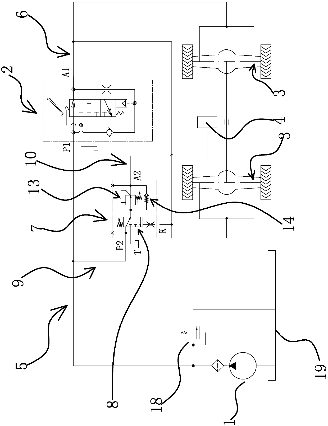
[0040] The full hydraulic reverse brake clutch system includes an oil pump 1, a brake valve 2, a brake 3, a transmission device 4 and a reverse brake clutch valve 7.
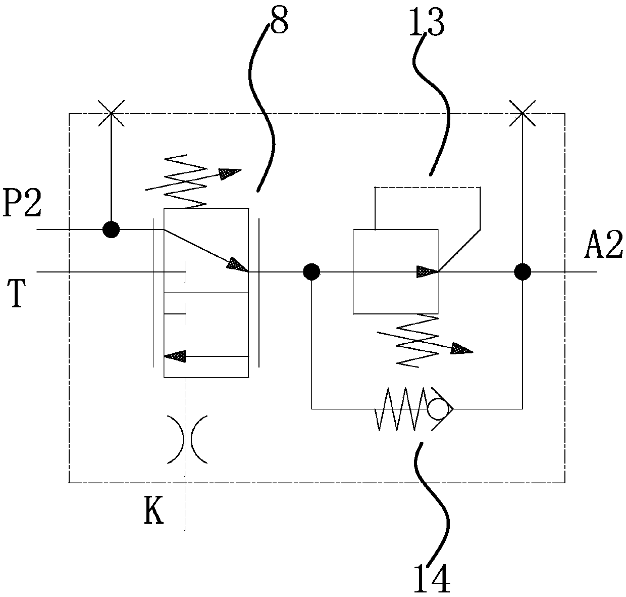
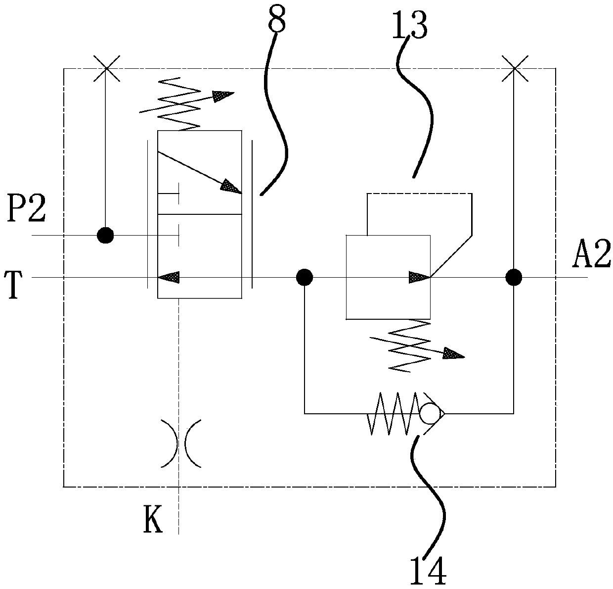
[0041] Specifically, as figure 1 As shown, the oil inlet end of the oil pump 1 is connected to the oil tank 19, and the oil outlet end is connected with the oil inlet P1 of the brake valve 2 through the oil inlet road-5, and a safety valve 18 is also arranged on the oil inlet road-5 to brake The working oil port A1 of the valve 2 communicates with the brake 3 through the working oil circuit-6. The brake valve 2 in this embodiment refers to a valve structure capable of reducing the oil pressure of the working oil passage-6 according to the increase of the stroke of the brake mechanism. The working oil circuit 16 supplies oil to the brake 3 to release the brake 3, and the brake 3 performs braking when the oil pressure of the working oil circuit 16 decreases. The reverse brake clutch valve 7 is between the oil pa...
Embodiment 2
[0049] The technical solution in this embodiment is basically the same as the technical solution in the first embodiment, the difference is that in this embodiment, the reverse brake clutch valve 7 is an integral structure. Such as Figure 4 and Figure 5 As shown, the reverse brake clutch valve 7 also includes a valve body 15 , and the hydraulically controlled reversing valve 8 , pressure reducing valve 12 and one-way valve 14 are all arranged in the valve body 15 .
[0050] Such as Figure 5 As shown, the hydraulic control reversing valve 8 includes a reversing valve chamber 8b and a reversing valve core 8c slidingly arranged in the reversing valve chamber 8b. The reversing valve chamber 8b has an oil inlet groove 8b1, a working oil groove 8b2 and an oil return groove 8b3. The pressure reducing valve 12 includes a pressure reducing valve cavity 13b and a pressure reducing valve core 13c slidably disposed in the pressure reducing valve cavity 13b. The pressure reducing valv...
Embodiment 3
[0055] The technical solution in the present embodiment is basically the same as the technical solution in the third embodiment, the difference is that in the present embodiment, such as Figure 5 As shown, the outer surface of the reversing valve core 8c has an oil return slot 8c1 that can communicate with the working oil tank 8b2 and the oil return tank 8b3. One end of the pressure reducing valve cavity 13b has a pressure reducing control oil cavity 13b3, and the pressure reducing valve core 13c has a The oil passage 13c1, one end of the oil passage 13c1 communicates with the decompression control oil chamber 13b3, and the other end communicates with the decompression valve chamber 13b through the oil passage 13c2 on the decompression valve core 13c, and the one-way valve chamber 14a is close to the return spring three One end of 14c communicates with the decompression oil tank 13b1, and communicates with the oil tank 13b2 and the working oil port 2 A2 through the decompressi...
PUM
 Abstract
Description
Claims
Application Information
 - R&D
- Intellectual Property
- Life Sciences
- Materials
- Tech Scout
- Unparalleled Data Quality
- Higher Quality Content
- 60% Fewer Hallucinations
Browse by: Latest US Patents, China's latest patents, Technical Efficacy Thesaurus, Application Domain, Technology Topic, Popular Technical Reports.
© 2025 PatSnap. All rights reserved.Legal|Privacy policy|Modern Slavery Act Transparency Statement|Sitemap|About US| Contact US: help@patsnap.com


