
Milling machine spindle

A milling machine spindle and bearing technology, applied in the directions of large fixed members, metal processing machinery parts, metal processing equipment, etc., can solve the problems of difficult assembly, poor assembly accuracy, complex structure, etc. The effect of cutting power

Pending Publication Date: 2018-10-19
隆昌精机有限公司
View PDF0 Cites 0 Cited by
  • Summary
  • Abstract
  • Description
  • Claims
  • Application Information

AI Technical Summary

Problems solved by technology

[0004] In view of the deficiencies in the prior art, the purpose of the present invention is to provide a milling machine spindle, which aims to solve the problems of complex structure, difficult assembly and poor assembly accuracy of the milling machine spindle in the prior art

Method used


Image

  • Milling machine spindle
  • Milling machine spindle

Examples


Embodiment Construction

[0020] The implementation of the present application will be described in detail below with reference to the accompanying drawings and examples, so as to fully understand and implement the implementation process of how the present application uses technical means to solve technical problems and achieve technical effects.

[0021] It should be noted that, in the case of no conflict, the embodiments in the present application and the features in the embodiments can be combined with each other.

[0022] In the description of the present invention, it should be understood that the orientations or positional relationships indicated by the terms "front", "rear", "inner" and the like are based on the orientations or positional relationships shown in the drawings, and are only for the convenience of describing the present invention and simplified descriptions, rather than indicating or implying that the device or element referred to must have a specific orientation, be constructed and ...


PUM


Abstract

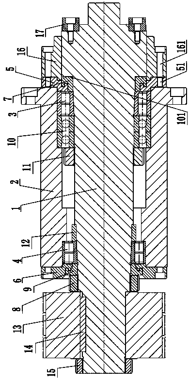
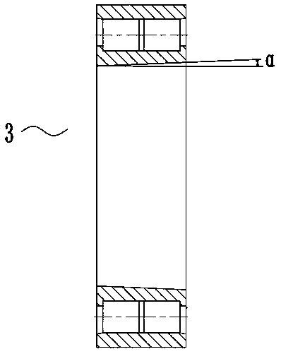
The invention provides a milling machine spindle. The milling machine spindle comprises a spindle sleeve, a first bearing, a second bearing, a spindle core, a first labyrinth end cover and a second labyrinth end cover. The first bearing and the second bearing are correspondingly sleeved with the front and rear ends in the spindle sleeve. The spindle core is sleeved with the first bearing and the second bearing. The first labyrinth end cover and the second labyrinth end cover are correspondingly arranged at the front and rear ends of the spindle sleeve. A first step surface for limiting the first labyrinth end cover is arranged on the portion, at the front side of the first labyrinth end cover, of the spindle core. A first nut for limiting the second labyrinth end cover is arranged on the portion, on the rear side of the second labyrinth end cover, of the spindle core. The inner walls of the first bearing and the second bearing each are a taper with a big front end and a small rear end.A tapered surface matched with the tapered inner walls of the first bearing and the second bearing is arranged on the spindle core. According to the milling machine spindle, the tapered bearings withthe inner walls with the big front ends and the small rear ends are arranged between the spindle sleeve and the spindle core, and the tapered surface matched with the tapered inner walls of the bearings is arranged on the spindle core, so that assembly positioning is facilitated and assembly precision is improved.

Description

technical field [0001] The invention relates to the technical field of machining, in particular to a milling machine spindle. Background technique [0002] A CNC milling machine refers to a machine tool that can mill a workpiece with a spindle. Its main components usually include a machine base, a worktable, a spindle, a spindle drive motor, a feed drive motor, and a fixture for fixing the workpiece; during operation, the spindle rotates The main movement is the main movement, and the relative movement between the workpiece and the spindle is the feed movement. A cutterhead is installed at the front end of the spindle, and the cutterhead is driven to process the workpiece through the rotation of the spindle. The main shaft of the existing milling machine is not only complicated in structure and not easy to assemble, but also has low assembly precision, high manufacturing cost, and poor cutting ability. [0003] Therefore, the prior art still needs to be improved and develop...

Claims


Application Information

Patent Timeline
IPC IPC(8): B23B19/02B23Q1/70
CPCB23Q1/70
Inventor 王玉林
Owner 隆昌精机有限公司
Learn More