Heat radiating module

A technology of heat dissipation module and heat dissipation fin, applied in cooling/ventilation/heating transformation, instrument cooling, instrument and other directions, can solve the problems of increasing production cost, removing clean chamfers, increasing processes, etc., to achieve convenient assembly and positioning, The effect of avoiding interference

Inactive Publication Date: 2008-01-02
FU ZHUN PRECISION IND SHENZHEN +1
View PDF0 Cites 2 Cited by
  • Summary
  • Abstract
  • Description
  • Claims
  • Application Information

AI Technical Summary

Problems solved by technology

However, it is difficult to remove the chamfer by hand, and it affects the appearance; CNC processing requires additional procedures and increases the production cost

Method used


Image

  • Heat radiating module
  • Heat radiating module
  • Heat radiating module

Examples


Embodiment Construction

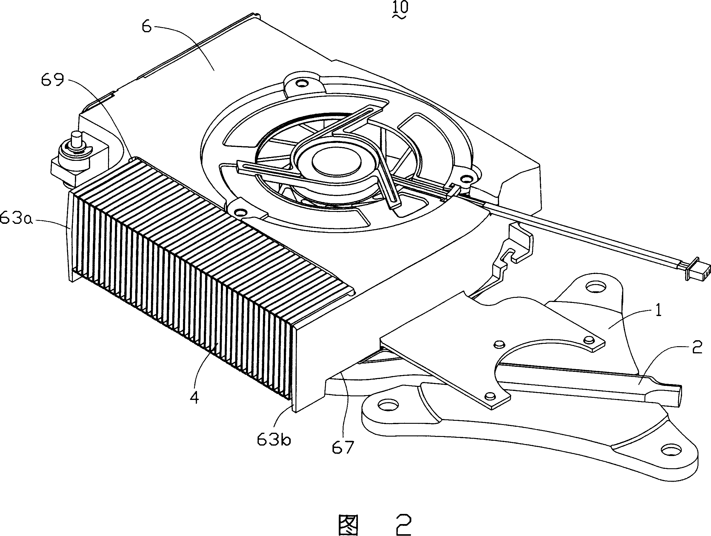
[0013] As shown in FIGS. 1 and 2 , the cooling module 10 includes a vapor chamber 1 , a heat pipe 2 , a fin set 4 and a centrifugal fan 6 . Wherein the fin set 4 is placed at the side end of the centrifugal fan 6 .

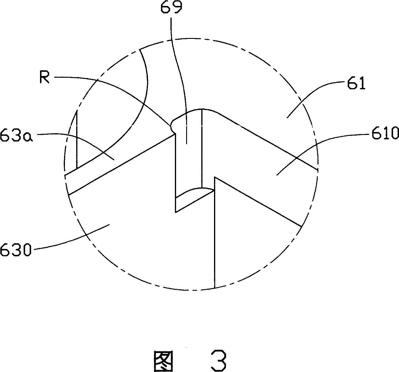
[0014] The fan 6 includes a fan frame 60 and a fan wheel set 68 disposed in the fan frame 60 . The fan frame 60 is integrally formed by injection molding. The fan frame 60 includes a top board 61 , a bottom board 62 and a side board 64 connected between the top board 61 and the bottom board 62 . Wherein, the top plate 61 , the bottom plate 62 and the side plate 64 jointly form a space for accommodating a fan wheel set 68 for generating airflow. The top plate 61 and the bottom plate 62 are arranged in parallel, and are respectively arranged on the upper and lower sides of the fan wheel set 68. A circular air inlet 65 is formed at the central position of the top plate 61 and the bottom plate 62, that is, facing the fan wheel set 68. The side plate 64 forms an air ...


PUM


Abstract

A heat radiator module comprises a fin group and a fan, wherein the fan comprises a fan frame and a fan wheel group in the fan frame. One side of the fan frame is provided with an air outlet, the fin group is provided at the air outlet, the fan frame extends at least one baffle plate outwards at the air outlet, the connection between the baffle plate and the fan frame is provided with a groove to avoid interference between the fin group and the fan in assembly, with simple assembly and positioning.

Description

technical field [0001] The invention relates to a heat dissipation module, in particular to a heat dissipation module suitable for heat dissipation of electronic components. Background technique [0002] At present, the problem of heat dissipation has become an important problem restricting the development of electronic components. The industry usually uses a heat dissipation module attached to the electronic component to dissipate heat. [0003] The existing heat dissipation module usually includes a centrifugal fan, several heat dissipation fins and a heat pipe connected between the heat generating electronic components and the heat dissipation fins. Wherein, the fan has a fan frame, and the fan frame forms an air outlet on one side. The heat dissipation fins are arranged in parallel, and are arranged at the air outlet of the fan frame to form a cuboid fin group, and the fin group abuts against the fan frame to position the fin group. [0004] However, the fan frame is u...

Claims


Application Information

Patent Timeline
Patent Type & Authority Applications(China)
IPC IPC(8): H05K7/20G12B15/06
Inventor 彭界波孟劲功黄清白洪锐彣
Owner FU ZHUN PRECISION IND SHENZHEN
Why Eureka
Try Eureka