
Rotor disk assembly and disk motor

A technology of rotor discs and components, applied in the direction of electric components, magnetic circuit rotating parts, electrical components, etc., can solve problems that affect the performance of disc motors, spend more energy on permanent magnets, and loose permanent magnet fixed discs, etc., to achieve Convenient positioning and assembly, avoid loosening, and reduce the effect of failure rate

Pending Publication Date: 2019-01-11
仪坤动力科技(上海)有限公司
View PDF0 Cites 3 Cited by
  • Summary
  • Abstract
  • Description
  • Claims
  • Application Information

AI Technical Summary

Problems solved by technology

The accuracy of the installation position of the permanent magnet can affect the performance of the disc motor. During the assembly process of the rotor disc assembly in the prior art, the assembler usually needs to spend more energy on positioning the permanent magnet, and in the prior art After long-term use of the rotor disk assembly, the permanent magnet is used to loosen relative to the fixed disk

Method used


Image

  • Rotor disk assembly and disk motor
  • Rotor disk assembly and disk motor
  • Rotor disk assembly and disk motor

Examples


Embodiment Construction

[0035] The following will clearly and completely describe the technical solutions in the embodiments of the present invention with reference to the accompanying drawings in the embodiments of the present invention. Obviously, the described embodiments are only part of the embodiments of the present invention, not all of them. Based on the embodiments of the present invention, all other embodiments obtained by persons of ordinary skill in the art without creative efforts fall within the protection scope of the present invention.

[0036] It should be noted that if there is a directional indication (such as up, down, left, right, front, back...) in the embodiment of the present invention, the directional indication is only used to explain the position in a certain posture (as shown in the accompanying drawing). If the specific posture changes, the directional indication will also change accordingly.

[0037] In addition, if there are descriptions involving "first", "second" and ...


PUM


Abstract

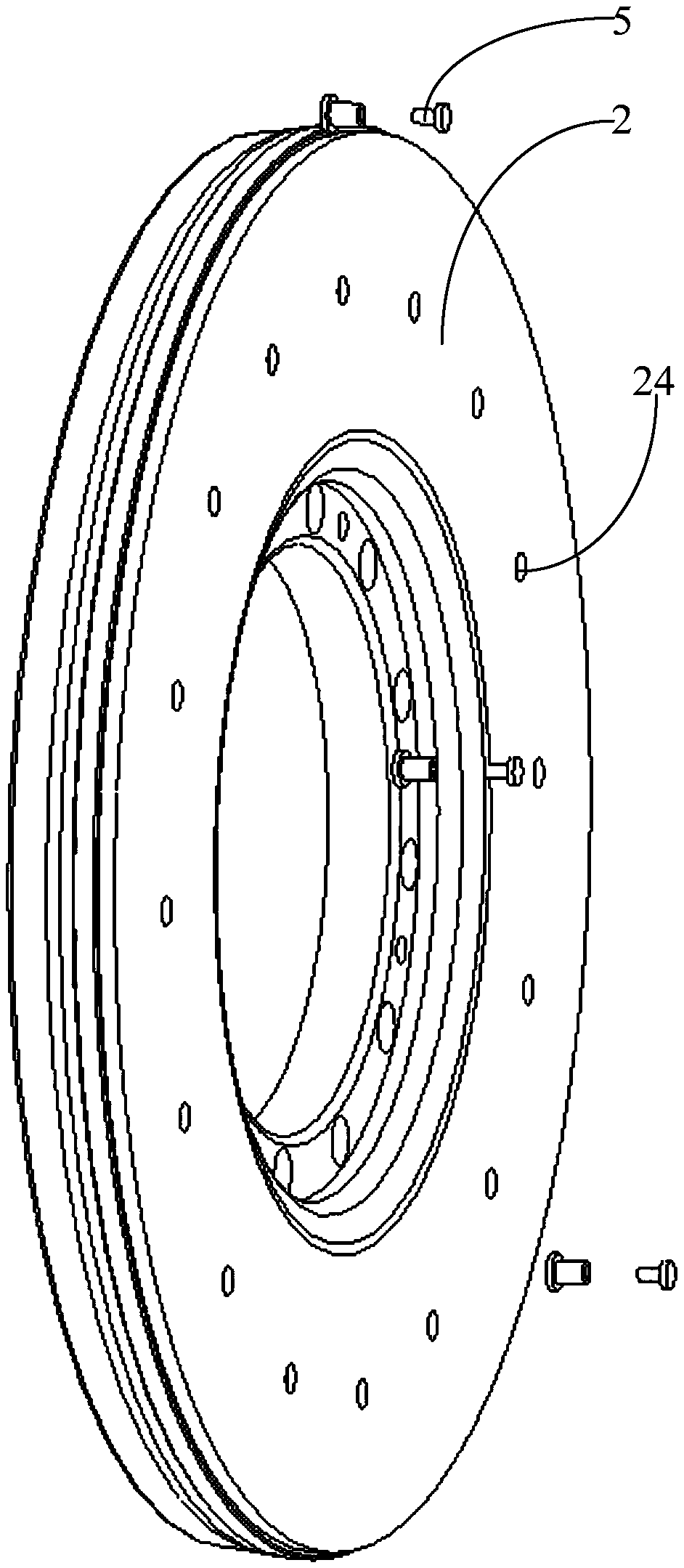
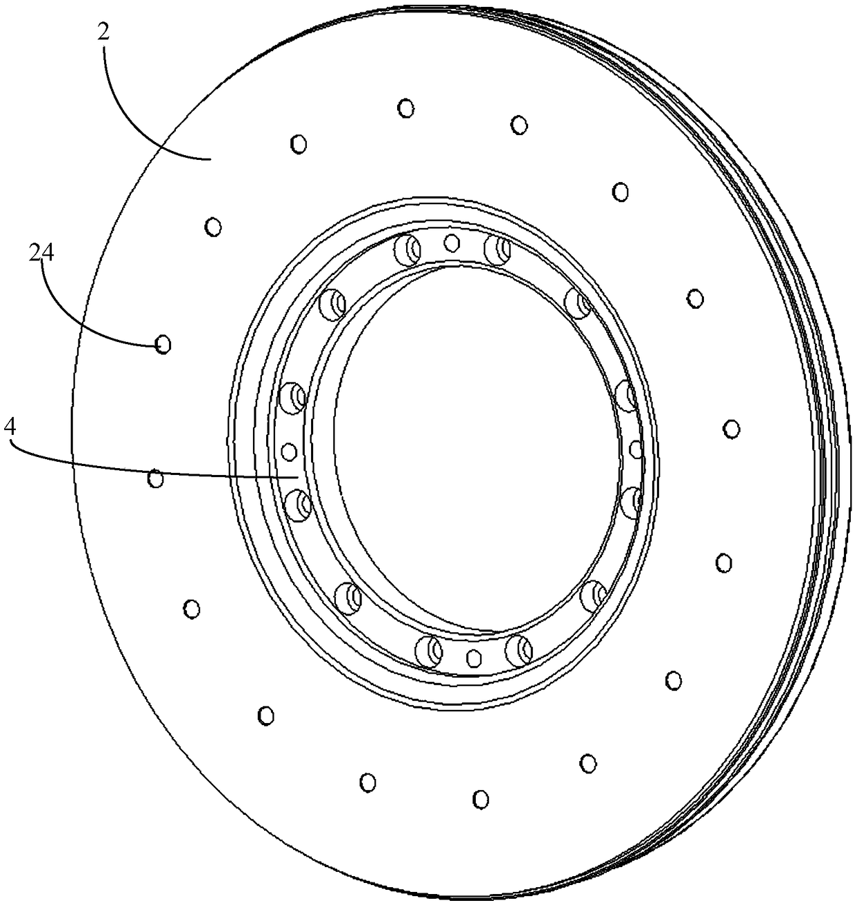
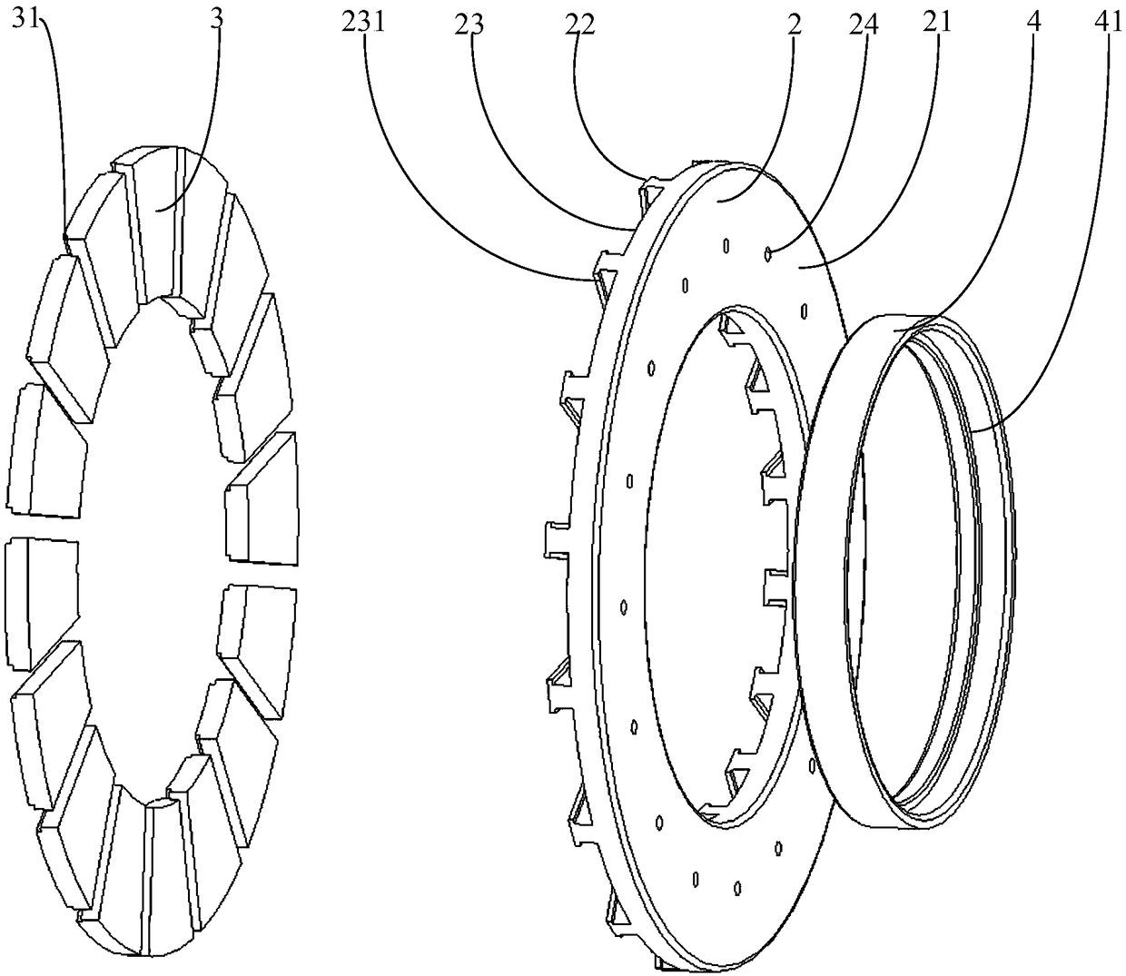
The invention provides a disc motor and a rotor disc assembly, wherein the rotor disc assembly comprises a fixed disc, an annular iron core, a plurality of permanent magnets and a fixed ring. The fixed disk is provided with an annular mounting groove, and the annular mounting groove is provided with an annular inner side wall, an annular outer side wall and a bottom wall. The annular iron core isinstalled in the annular mounting groove, the annular iron core has a first end face and a second end face, and the second end face of the annular iron core is concave with a plurality of limiting grooves. The plurality of permanent magnets are embedded and installed in the plurality of limiting grooves, each limiting groove is adapted to correspond to the shape of the permanent magnets to preventthe permanent magnets from moving along the axial direction of the annular iron core, and each of the plurality of permanent magnets has a proximal end and a distal end. The fixing ring abuts againsta proximal end of the plurality of permanent magnets. The invention can facilitate assembling of the rotor disk assembly by an assembler and avoid loosening of the permanent magnet relative to the fixed disk.

Description

technical field [0001] The invention relates to the technical field of motors, in particular to a rotor disc assembly and a disc motor. Background technique [0002] Disk motors have a high torque density and have broad application prospects. Disk motors generally include a rotor disk assembly, and the rotor disk assembly generally includes a fixed disk and a permanent magnet mounted on the fixed disk. The accuracy of the installation position of the permanent magnet can affect the performance of the disc motor. During the assembly process of the rotor disc assembly in the prior art, the assembler usually needs to spend more energy on positioning the permanent magnet, and in the prior art After long-term use of the rotor disk assembly, the permanent magnets are used to loosen relative to the fixed disk. Contents of the invention [0003] The main purpose of the present invention is to propose a rotor disc assembly and a disc motor, aiming at ensuring the installation accu...

Claims


Application Information

Patent Timeline
IPC IPC(8): H02K1/27H02K1/28
CPCH02K1/2793H02K1/28
Inventor 彭兵薛佳运
Owner 仪坤动力科技(上海)有限公司
Learn More