Cylindrical coordinate and rectangular coordinate combined archwire bending robot and using method thereof

A Cartesian coordinate and robot technology, applied in medical science, dentistry, orthodontics, etc., can solve the problems of robot interference in orthodontic arch wire bending, reduce the quality of orthodontic arch wire, hinder the bending process, etc., and achieve a reduction in bending The effect of reducing the difficulty of planning, improving the accuracy of arch wire bending, and reducing the difficulty of control

Inactive Publication Date: 2018-10-19
HARBIN UNIV OF SCI & TECH
View PDF4 Cites 0 Cited by
  • Summary
  • Abstract
  • Description
  • Claims
  • Application Information

AI Technical Summary

Problems solved by technology

[0003] For example, the orthodontic archwire bending robots described in the invention patent authorization announcement number of CN 103892929 B and the utility model patent authorization announcement number of CN203898469 U all adopt the Cartesian coordinate movement mode, mainly moving in three directions of the Cartesian coordinates. Based on this, some degrees of freedom are added to complete the corresponding bending operation, and then the design of the motion scheme of the entire orthodontic archwire bending robot is completed. However, in the actual bending process, due to the certain spatial structure of the formed part, the feeding The wire will occupy a large space during the rotation process, which makes the orthodontic archwire bending robot prone to interference and hinders the bending process. The mold cannot clamp the orthodontic archwire. Therefore, during the bending process of the orthodontic archwire bending robot, there is a bending gap between the chuck of the bending mold and the orthodontic archwire. The bending gap will cause the orthodontic archwire Sliding and warping occurs at the deformed part, which further reduces the quality of the orthodontic archwire bending robot, making it impossible for the orthodontic archwire bending robot to bend the ideal orthodontic archwire
Due to the structural limitations of the Cartesian coordinate orthodontic archwire bending robot, it is easy to interfere and slip and warp during the bending process, so that the Cartesian coordinate orthodontic archwire bending robot can only bend the first sequence Curves and individual second-sequence tunes, which cannot meet the requirements of doctors and patients for all second-sequence tunes
[0004] Similarly, although the Cartesian coordinate type orthodontic archwire bending robot whose utility model patent authorization announcement number is CN 204562423 U can bend the T-shaped bend by changing the radius of curvature of the orthodontic archwire bending angle, the Cartesian coordinate The orthodontic archwire bending robot combined with the traditional bending method still cannot avoid the limitations of the Cartesian coordinate structure, so that the orthodontic archwire bending robot cannot surpass the manual bending, and cannot break through the orthodontic archwire bending robot. Key Technical Difficulties
[0005] A similar patent also has a bending device for an orthodontic archwire bending robot with the authorized announcement number CN 205324558 U. This patent realizes the clamping and feeding of the orthodontic archwire through the positive and negative rotation of the motor , but the bending device has a complex structure, and can only realize the clamping and loosening of the orthodontic archwire, and cannot bend complex sequence curves. Compared with the above two rectangular coordinate-type orthodontic archwire bending robots, this patent Limited functions, small scope of application
[0006] A comprehensive analysis of the existing orthodontic arch wire bending robots can only achieve the bending of the first sequence of bows and a few simple second sequence of bending, while dental wire bending technicians can flexibly bend such as Omega, Arch wires with special shapes such as T-shaped curves, teardrop curves, and box-shaped curves are used for clinical treatment. In addition, dental wire bending technicians can bend personalized orthodontic arch wires according to the actual conditions of different patients. Orthodontic archwires need to contain one or more special functional curves of the second and third sequences, with different structural complexity, including various types and numbers of the second and third sequences of curves, and in bending personalized orthodontics When archwire is used, the bending space is narrow, which makes the orthodontic archwire robot prone to interference problems during the bending process. Therefore, the development of orthodontic archwire robot technology is restricted.
In addition, in the actual arch wire bending process, the bending mold used by the rectangular coordinate orthodontic arch wire bending robot cannot clamp the orthodontic arch wire so that a bending gap is generated during the bending process, resulting in slippage and warping. This kind of bending method also causes the bent orthodontic archwire to be in the cantilever beam state, which affects the bending accuracy of the orthodontic archwire bending robot. By comparing the above-mentioned existing Cartesian coordinate formula Orthopedic archwire robot, designed a combined cylindrical coordinate and rectangular coordinate archwire bending robot

Method used


Image

  • Cylindrical coordinate and rectangular coordinate combined archwire bending robot and using method thereof
  • Cylindrical coordinate and rectangular coordinate combined archwire bending robot and using method thereof
  • Cylindrical coordinate and rectangular coordinate combined archwire bending robot and using method thereof

Examples


Embodiment 1

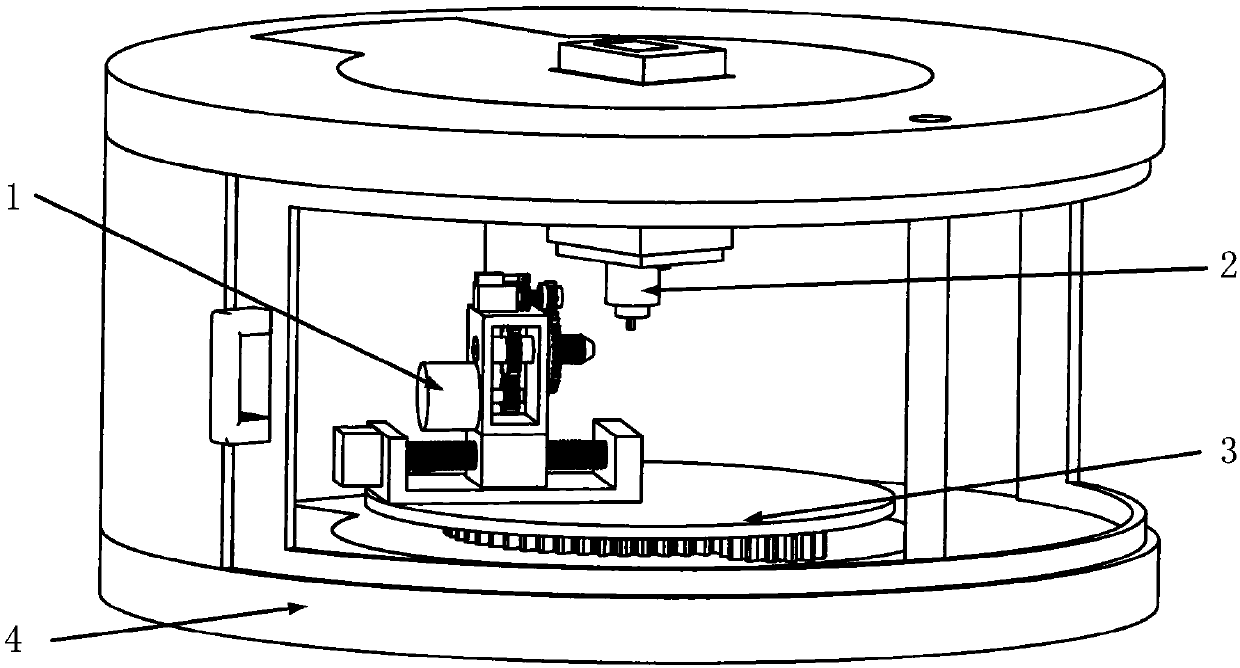
[0029] Embodiment 1: as figure 1 , figure 2 , image 3 , Figure 4 , Figure 5 , Figure 6 , Figure 7 , Figure 8 As shown, this embodiment adopts the following technical solutions:

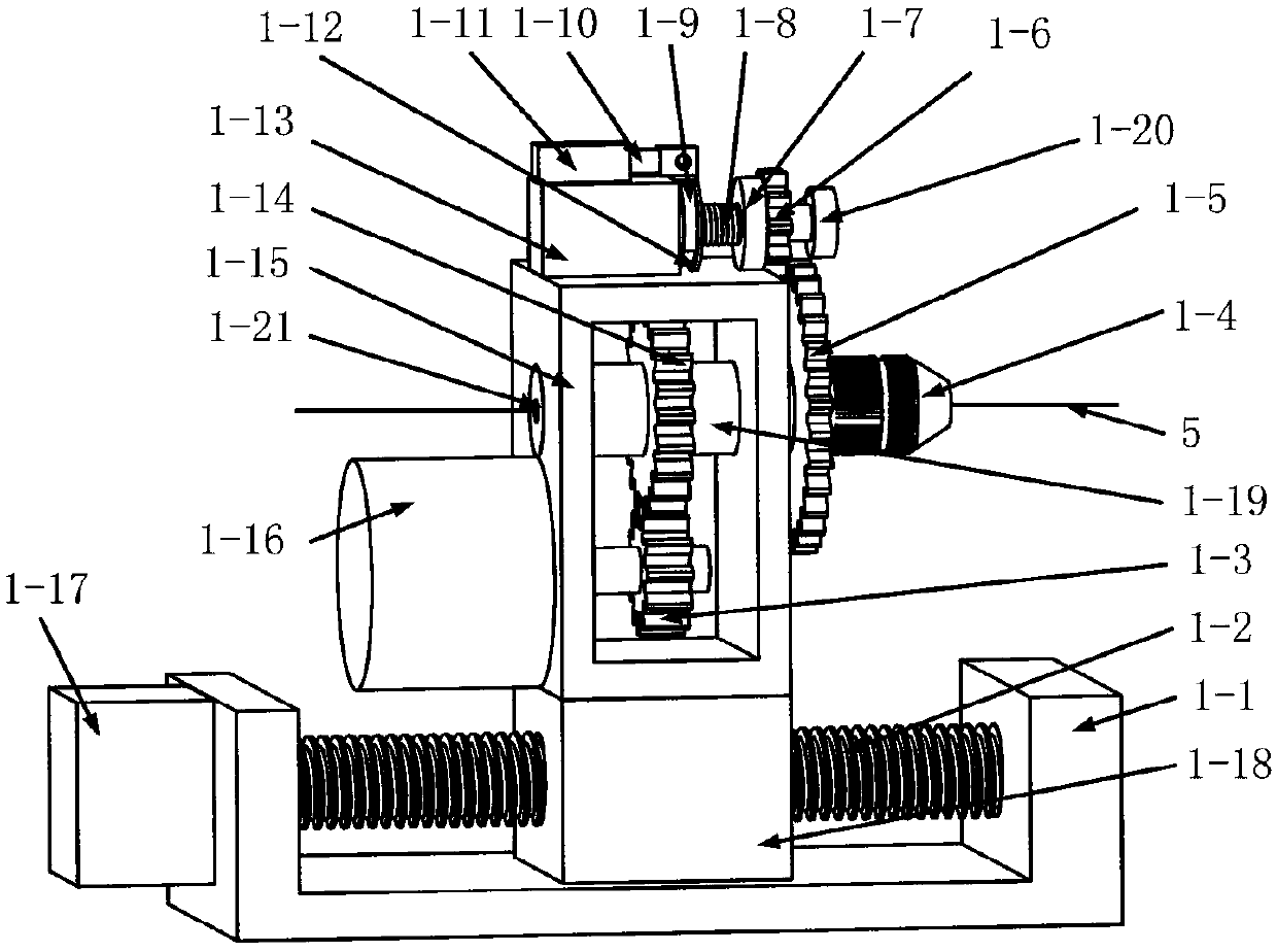
[0030] The arch wire bending robot combined with cylindrical coordinates and rectangular coordinates and its use method is composed of four parts: clamp I1, clamp II2, cylindrical coordinate system turntable 3, and robot main body shell 4: clamp I in clamp I1 The lead screw guide rail slide table 1-1 is connected to the turntable 3-3 in the cylindrical coordinate system turntable 3 through bolts, and the turntable 3-3 of the cylindrical coordinate system turntable 3 is connected to the connection chassis 4-6 inside the robot main body shell 4 through bolts. Connection, clamp II 2 is fixed on the top 4-7 of the outer shell of the robot main body shell 4 through bolt connection; the clamp I1 belongs to the cylindrical coordinate type, and it includes: clamp I lead screw guide rail slide 1-...

Embodiment 2

[0036] Embodiment 2: Define the initial power-on position of the orthodontic archwire bending robot;

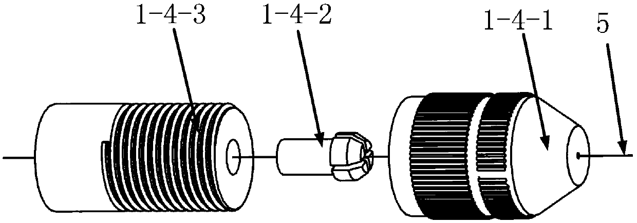
[0037] According to the device described in Embodiment 1, when the orthodontic archwire bending robot is in the initial power-on state, the clamp I linear motor push rod 1-11 in the clamp I1 is in the initial state of not being pushed out, and the clamp I clamps the motor 1-13. Clamp I rotary motor 1-16 and clamp I lead screw motor 1-17 are in the standby state, and the distance between clamp I lead screw nut 1-18 and clamp I lead screw motor 1-17 is the clamp Ⅰ The initial position of the screw nut 1-18, the pincer Ⅰ clamps the driven gear 1-5 and the pincer Ⅰ clamps the driving gear 1-6 is in a non-meshing state, and the pincer I clamps the chuck core in the tapered chuck 1-4 1-4-2 is in the non-clamping state; the linear motor 2-5 in the clamp II 2, the screw motor 2-9 in the clamp II and the rotary motor 2-12 in the clamp II are all in the standby state, and the screw nut...

Embodiment 3

[0038] Embodiment 3: The specific implementation of the orthodontic archwire robot to complete the automatic wire feeding task;

[0039] According to the device described in Example 1, when the dental wire bending technician needs the orthodontic archwire robot to complete the automatic wire feeding task, the specific implementation method is: before the wire feeding task is performed, the orthodontic archwire robot is in the initial power-on state, The clamp I linear motor push rod 1-11 in the clamp I1 is still in the initial state that has not been pushed out, the clamp I clamping motor 1-13, and the clamp I rotating motor 1-16 are still in the initial state and remain in the standby state, and the clamp I clamps The passive gear 1-5 is in a non-meshing state with the active gear 1-6 clamped by pliers Ⅰ, and the clamp core 1-4-2 in the tapered chuck 1-4 of pliers Ⅰ is in a non-clamping state. When dental wire bending The technician sends the orthodontic archwire 5 from the w...


PUM


Abstract

The invention discloses a cylindrical coordinate and rectangular coordinate combined archwire bending robot and a using method thereof, and relates to the field of orthodontic treatment equipment. Theorthodontic archwire bending robot combines cylindrical coordinate and rectangular coordinate, and comprises four parts: a clamp I, a clamp II, a cylindrical coordinate system turntable, and a robotmain body cover. The cylindrical coordinate clamp I and the rectangular coordinate clamp II realize the bending of a bending point and the position adjustment of a clamping point. Compared with a rectangular orthodontic archwire bending robot, the bending efficiency and the bending effect are improved, the cylindrical coordinate and rectangular coordinate combined archwire bending robot can replace a dental technician who bends the orthodontic archwire to conduct orthodontic archwire bending work. The burden of the technician who bends the orthodontic archwire.

Description

Technical field: [0001] The present invention relates to the field of orthodontic treatment equipment, in particular to an arch wire bending robot combined with cylindrical coordinates and rectangular coordinates and a method of use thereof, which are used for bending orthodontic arch wires instead of dental wire bending technicians. Background technique: [0002] Malocclusion is a kind of oral disease with irregular arrangement of teeth, abnormal relationship between teeth and jaws between the upper and lower dental arches, and abnormal size, shape and position of the jaw, which seriously endangers the physical and mental health of human beings. Wearing an orthodontic archwire is the most common and effective treatment for malocclusion. The bent orthodontic archwire exerts an orthodontic force on the brackets bonded to the teeth, so that the teeth move to achieve correction. The precise bending and shaping of the orthodontic archwire is the key to orthodontic treatment. Or...

Claims


Application Information

Patent Timeline
IPC IPC(8): A61C7/02
CPCA61C7/02
Inventor 姜金刚闵兆伟黄致远霍彪马雪峰张永德
Owner HARBIN UNIV OF SCI & TECH
Why Eureka
Try Eureka