Suction tube

A straw and suction pipe technology, applied in the field of straws, can solve problems such as limited length of life straws, human health hazards, unfavorable energy conservation and environmental protection, etc., to achieve the effects of ensuring sealing, improving taste, and removing odors

Inactive Publication Date: 2018-10-19
方星
View PDF0 Cites 0 Cited by
  • Summary
  • Abstract
  • Description
  • Claims
  • Application Information

AI Technical Summary

Problems solved by technology

[0002] In wild survival, it is very important to obtain safe and hygienic drinking water at any time. Due to the lack of power equipment in the wild, usually only portable equipment can be used to obtain safe and clean water. However, the amount of water carried at any time is often limited and urgently needed A device that can purify field water in time, so the life straw appeared, which is mainly used for drinking water in the field. Because the water in the field has not been treated, it is harmful to human health, and the life straw can purify the water in the field. Water resources, in order to directly obtain safe and hygienic drinking water from the wild. At present, there are many life straws on the market, but the existing life straws are too simple in structure. The use requirements of special groups of people, and most of the existing life straws are disposable devices. When the water purification effect drops, you can only replace them with new ones, which is not conducive to energy saving and environmental protection. Moreover, the length of the life straw is limited, and you need to lie on the water surface when using it. There is a danger of drowning if used on

Method used


Image

  • Suction tube
  • Suction tube
  • Suction tube

Examples


Embodiment Construction

[0012] The following will clearly and completely describe the technical solutions in the embodiments of the present invention with reference to the accompanying drawings in the embodiments of the present invention. Obviously, the described embodiments are only some, not all, embodiments of the present invention. Based on the embodiments of the present invention, all other embodiments obtained by persons of ordinary skill in the art without making creative efforts belong to the protection scope of the present invention.

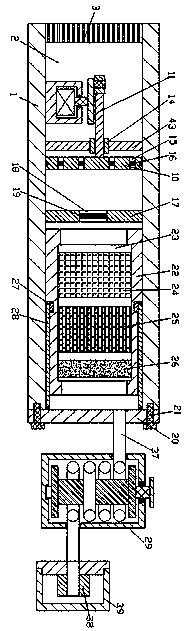
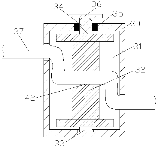
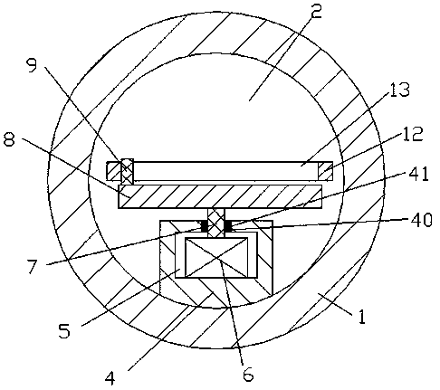
[0013] see Figure 1-3 , an embodiment provided by the present invention: a suction pipe, including a suction pipe body 1, a left and right through water suction space 2 is arranged inside the water suction pipe body 1, and a filter screen 3 is arranged at the opening of the left end of the water suction space 2 , the filter screen 3 is fixedly connected to the inner wall of the pumping space 2, a driving box 4 is fixedly arranged on the left side of the lower...


PUM


Abstract

The invention discloses a suction tube which comprises a water drawing tube. A water drawing space which is through in the left-right directions is arranged inside the water drawing tube, a filter screen is arranged at an opening in the left end of the water drawing space, a water purifying shell is arranged on the right side of the inside of the water drawing space, a water purifying space whichis through in the left-right directions is arranged inside the water purifying shell, an activated carbon layer, a resin layer and an ultra-filtration element are sequentially arranged inside the water purifying space from left to right, a twisted rope device is arranged on the right side of the water drawing tube, a sealing suction opening is connected with the right end of a connecting tube, anda sealing cover sleeves the right side of the sealing suction opening. The suction tube has the advantages that the sealing cover can be opened when the suction tube works, then water can be drunk via the sealing suction opening, and the suction tube is favorable for the field water drinking safety; a sealing plate can be opened, accordingly, the water purifying shell can be taken out, devices inthe water purifying space can be conveniently replaced and maintained, the service lives of the devices can be guaranteed, and the production cost can be saved.

Description

technical field [0001] The invention relates to the field of fire fighting and lifesaving, in particular to a straw. Background technique [0002] In wild survival, it is very important to obtain safe and hygienic drinking water at any time. Due to the lack of power equipment in the wild, usually only portable equipment can be used to obtain safe and clean water. However, the amount of water carried at any time is often limited and urgently needed A device that can purify field water in time, so the life straw appeared, which is mainly used for drinking water in the field. Because the water in the field has not been treated, it is harmful to human health, and the life straw can purify the water in the field. Water resources, in order to directly obtain safe and hygienic drinking water from the wild. At present, there are many life straws on the market, but the existing life straws are too simple in structure. The use requirements of special groups of people, and most of the...

Claims


Application Information

Patent Timeline
IPC IPC(8): A47G21/18
CPCA47G21/18
Inventor 方星
Owner 方星
Why Eureka
Try Eureka