Selective harmonic eliminated pulse width modulation-based DC bus voltage fluctuation compensation method
A DC bus voltage, pulse width modulation technology, applied in the control of electromechanical brakes, control of electromechanical transmissions, control of generators, etc., can solve the problems of long control period, low switching frequency, harmonics affecting control performance, etc. Wave characteristics, small output voltage harmonics, reducing low-frequency harmonic currents and the effect of output torque fluctuations
- Summary
- Abstract
- Description
- Claims
- Application Information
AI Technical Summary
Problems solved by technology
Method used
Image
Examples
Embodiment 1
[0026] The DC bus voltage fluctuation compensation method based on the selected harmonic elimination pulse width modulation includes the following steps:
[0027] 101) Voltage vector conversion step: converting a given voltage vector generated by standard vector control into polar coordinates to obtain a voltage vector in polar coordinates. On the one hand, the phase of the given voltage vector generates a synchronous trigger signal, which is used to start each control cycle, obtain start-up vector control and DC bus voltage fluctuation sampling; Used to generate the raw pulse trains for each phase.
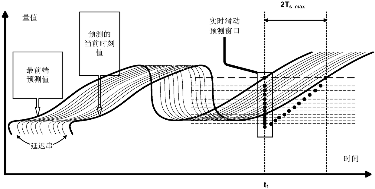
[0028] 102) Sampling and predicting step: formed by predicting the voltage vector in polar coordinates, and delaying the waveform of the given voltage vector by a certain execution cycle time from the current moment to obtain the predicted waveform. Among them, each prediction of the predicted waveform needs the bus voltage information to be ready at the beginning of the executi...
Embodiment 2
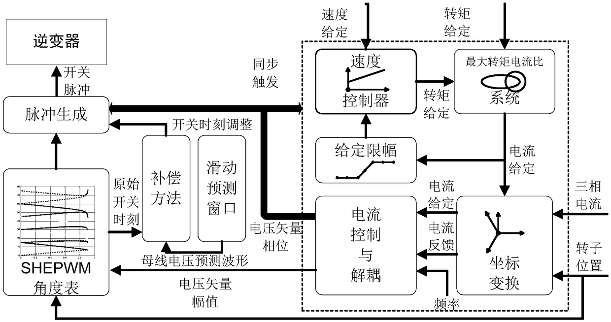
[0041] Such as figure 1 Shown is the overall schematic diagram of the system structure. The dotted box on the right is the standard vector control process. The given voltage vector finally generated by vector control is transformed into polar coordinates. On the one hand, the phase of the given voltage vector generates a synchronous trigger signal, which is used to start each control cycle, start vector control calculation and DC bus voltage fluctuation compensation; to generate the original pulse train for each phase. The angle adjustment value obtained by DC bus voltage fluctuation compensation acts on the original pulse sequence, and finally generates the compensated pulse sequence. The phases of the above synchronous trigger signals are consistent with the boundaries of the synchronous processing intervals to be described later, so as to ensure that each control result is applicable to the execution of the next interval.
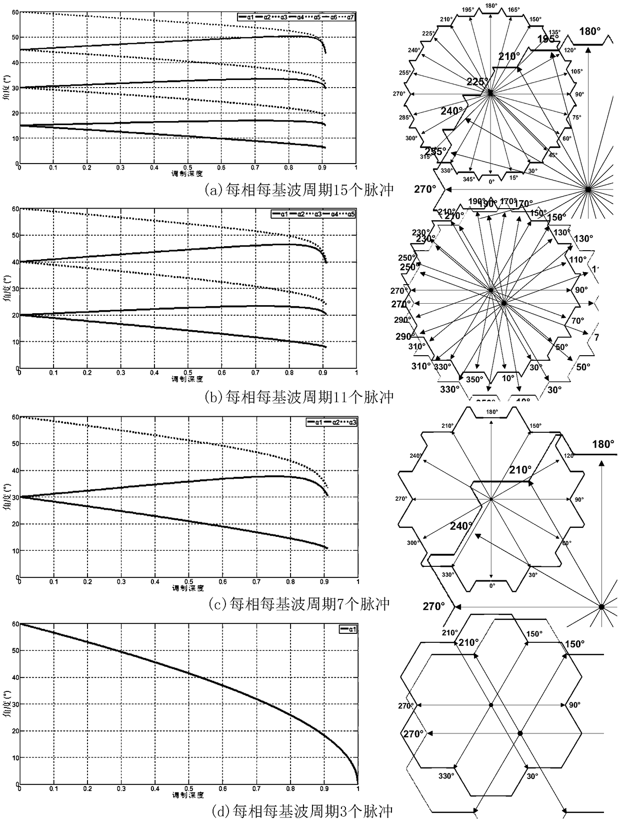
[0042] Such as Figure 2 to Figure 4 As shown...
PUM
 Abstract
Description
Claims
Application Information
 - Generate Ideas
- Intellectual Property
- Life Sciences
- Materials
- Tech Scout
- Unparalleled Data Quality
- Higher Quality Content
- 60% Fewer Hallucinations
Browse by: Latest US Patents, China's latest patents, Technical Efficacy Thesaurus, Application Domain, Technology Topic, Popular Technical Reports.
© 2025 PatSnap. All rights reserved.Legal|Privacy policy|Modern Slavery Act Transparency Statement|Sitemap|About US| Contact US: help@patsnap.com


