Al technical title is built by PatSnap Al team. It summarizes the technical point description of the patent document.
An inverter and single-motor technology, which is applied in the field of single-motor inverter assembly, can solve problems such as difficulty in meeting vehicle requirements and regulatory requirements, low power density, and poor safety, and achieve compact structure and high power density , high safety effect
Active Publication Date: 2018-10-16
CHINA FIRST AUTOMOBILE
View PDF4 Cites 13 Cited by
Summary
Abstract
Description
Claims
Application Information
AI Technical Summary
This helps you quickly interpret patents by identifying the three key elements:
Problems solved by technology
Method used
Benefits of technology
Problems solved by technology
[0003] Many inverters in the prior art are characterized by large volume, low power density, low integration, poor safety, etc., and it is difficult to meet the increasingly stringent vehicle requirements and regulatory requirements
Method used
Image
Click on the blue label to locate the original text in one second.
Reading with bidirectional positioning of images and text.
Examples
Embodiment 1
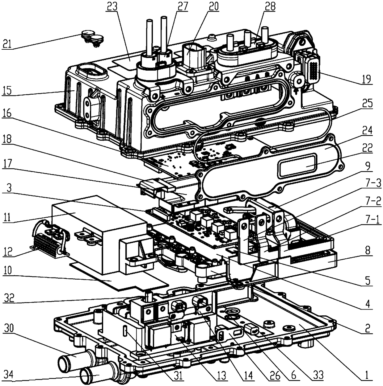
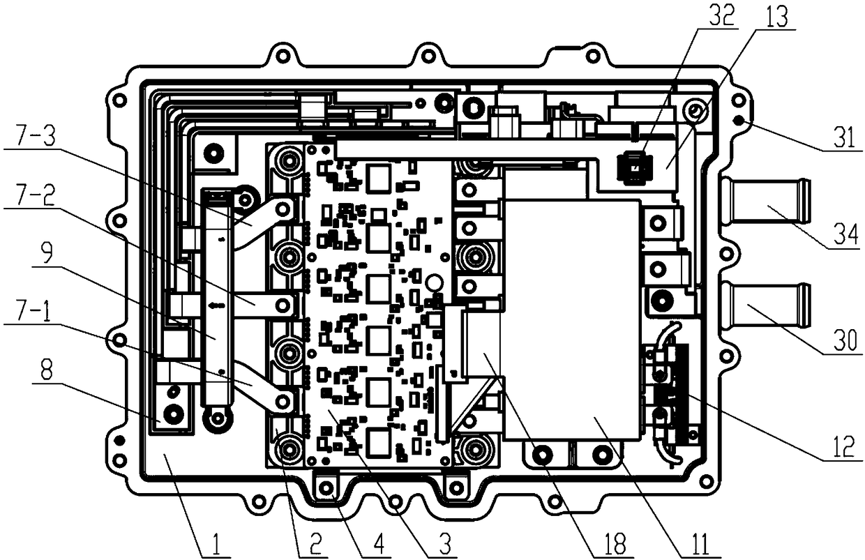
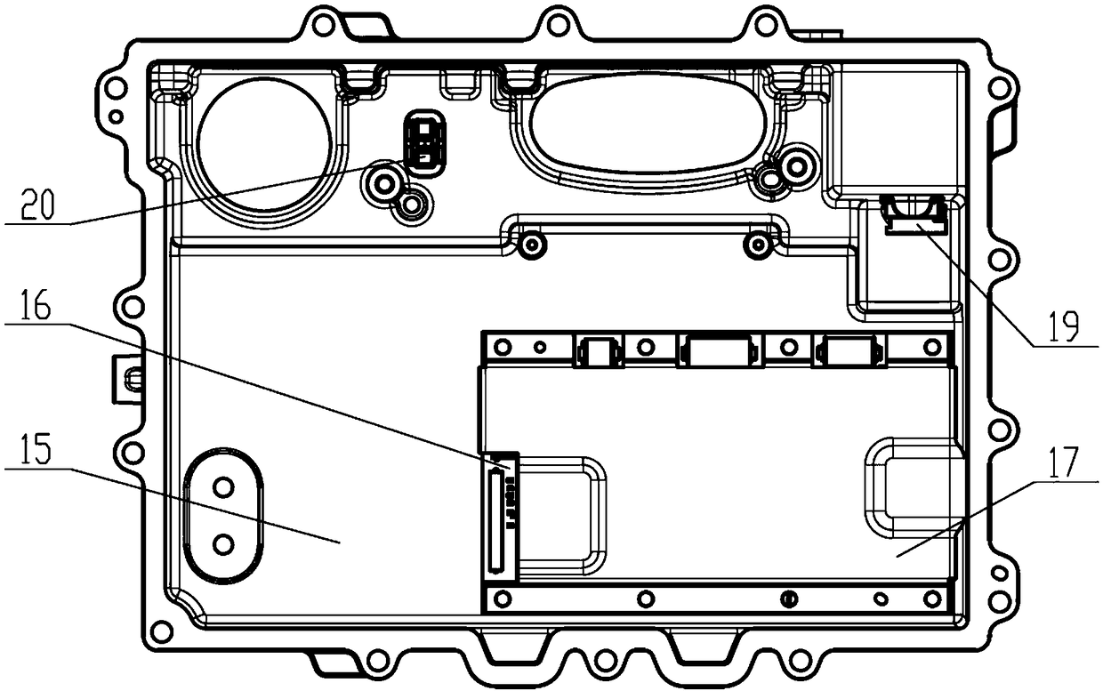
[0033] This embodiment provides a single-motor inverter assembly, which includes a main box 1, an IGBT module 2, a drive board 3, a drive board heat dissipation bracket 4, a drive board heat dissipation gasket 5, an O-ring 6, a three-phase Busbar 7 (including U-phase busbar 7-1, V-phase busbar 7-2, W-phase busbar 7-3), three-phase busbar fixing bracket 8, current sensor 9, DC bus capacitor cooling gasket 10, DC bus capacitor 11, discharge resistor 12, DC bus terminal block assembly 13, upper box body 15, control panel 16, shielding cover 17, flat cable 18, low-voltage signal connector 19, high-voltage air conditioner connector 20, pressure balance element 21. Product label 22, warning label 23, inverter end cover 24, inverter end cover sealing ring 25, end cover interlock connector 26, high voltage DC connector 27 and high voltage AC connector 28.
[0034] The main box body 1 is formed by die-casting, wherein a water inlet channel and an outlet channel are formed, the water in...
PUM
Abstract
The invention discloses a single-motor inverter assembly. The single-motor inverter assembly comprises a main box, an IGBT module, a driving board, a driving board heat dissipation gasket, a three-phase bus, a three-phase bus fixing bracket, a current sensor, a DC bus capacitor, a discharge resistance, a DC bus connection seat assembly, an upper box, a control board, a shielding cover, a flat cable, a high-voltage direct current connector and a high-voltage alternating current connector. The single-motor inverter assembly adopts a direct-current bus bar wiring seat assembly, so that the integrated level of the single-motor inverter is higher, and the structure is more compact; the parts such as the IGBT module, the capacitor, the DC bus bar connection seat assembly, the control board and the like are respectively arranged on the main box body and the upper box body according to a specific position, and the space is fully utilized, so that the volume is smaller and the power density ishigher; the capacitor, the direct current bus bar connection seat assembly, the direct current bus fixing bracket and the control board are positioned so that the assembly is more convenient; the control board is provided with the shielding cover, and the direct current input end is connected with a Y capacitor, so that the electromagnetic compatibility is better; the high-pressure air-conditioning connector and the fuse are integrated, and a structure for supplying power to the air-conditioning compressor is not needed, and the integration level is higher.
Description
technical field [0001] The invention belongs to the field of inverters, in particular to a single-motor inverter assembly. Background technique [0002] With environmental pollution and consumption of petroleum energy, the development of electric vehicles has become a consensus, especially after the introduction of stricter emission regulations, the development of electric vehicles is imminent. As a key component of electric vehicles, inverters have higher requirements. [0003] Many inverters in the prior art are characterized by large volume, low power density, low integration, poor safety, etc., and it is difficult to meet the increasingly stringent vehicle requirements and regulatory requirements. Contents of the invention [0004] In view of the shortcomings of the above existing technical solutions, the purpose of the present invention is to provide a single-motor inverter assembly with high power density, which can not only satisfy the convenience of vehicle layout...
Claims
Application Information
Patent Timeline
Application Date:The date an application was filed.
Publication Date:The date a patent or application was officially published.
First Publication Date:The earliest publication date of a patent with the same application number.
Issue Date:Publication date of the patent grant document.
PCT Entry Date:The Entry date of PCT National Phase.
Estimated Expiry Date:The statutory expiry date of a patent right according to the Patent Law, and it is the longest term of protection that the patent right can achieve without the termination of the patent right due to other reasons(Term extension factor has been taken into account ).
Invalid Date:Actual expiry date is based on effective date or publication date of legal transaction data of invalid patent.