Box-type steel column splice joint and mounting method thereof

An installation method and section steel technology, applied in the direction of building, building structure, etc., can solve the problems of large dislocation of upper and lower sections, reduce on-site welding, and low splicing efficiency of box-shaped steel columns, so as to improve the quality and achieve equal strong connection. Effect

Pending Publication Date: 2018-10-16
ZHONGYE-CHANGTIAN INT ENG CO LTD
View PDF7 Cites 11 Cited by
  • Summary
  • Abstract
  • Description
  • Claims
  • Application Information

AI Technical Summary

Problems solved by technology

At present, the on-site connection of steel structure buildings in my country, such as column-to-column splicing, beam-to-beam splicing, and beam-to-column connection, is still dominated by on-site welding or bolt-welding hybrid connections, and is mostly based on the "Multi-high-rise Civil Building Steel Structure Node Structure Details" "(16G519) selection, among them, such as Figure 1 to Figure 3 As shown, the splicing joints of box-shaped steel columns traditionally adopt the upper and lower ear plates 6, and use the double-plywood bolt connection method for positioning. This traditional connection positioning is simple and practical for small-section steel columns, and for large or extra-large , because the welding deviation of the upper and lower ear plates 6 and the adverse effects of the double splint misalignment were not considered, the problem of large misalignment of the upper and lower section columns often occurred on site, resulting in low splicing efficiency of box-shaped steel columns and affecting the splicing quality of box-shaped steel columns. It is difficult to ensure high-quality completion of the welding treatment and stiffening of the steel column section, resulting in the splicing of the column often becoming a structural short board
[0004] In addition, for the on-site assembly of steel columns and the connection between columns and beams in steel structure buildings, China Metallurgical Construction Research Institute reduces on-site welding by setting joint areas on the upper and lower columns, or completely avoids on-site welding through high-strength bolt connections instead of traditional splicing The temporary fixation of the upper and lower columns is realized through the lug plate 6 and the connecting plate 7 in the node, but this application is mostly for industrial and civil steel buildings that bear conventional loads, and the cross-section of the box-shaped steel column is small, so the internal reinforcement of the column is not considered
For super high-rise steel structure buildings, steel columns of special steel structures with special loads and high safety levels, due to their large cross-section (short side ≥ 1.5m), stiffeners need to be set in the cross-section, and the splicing joint is adopted. The treatment of stiffeners at joints should also be considered, and for special steel structures that bear dynamic loads, such as mine derricks, steel structure bridges and other structures, it is required to use first-level groove full penetration welds to achieve equal strength connections between upper and lower columns; according to " Standards for Acceptance of Construction Quality of Steel Structure Engineering "GB50205 Design Requires Full Penetration Primary and Secondary Welds Should Use Ultrasonic Flaw Detection for Internal Defect Inspection. When Ultrasonic Flaw Detection Cannot Make Defects, Radiographic Flaw Detection Should Be Used At present, there are almost no on-site splicing technical solutions for box-section columns of such steel structures.

Method used


Image

  • Box-type steel column splice joint and mounting method thereof
  • Box-type steel column splice joint and mounting method thereof
  • Box-type steel column splice joint and mounting method thereof

Examples


Embodiment Construction

[0032] In order to facilitate the understanding of the present invention, the present invention will be described in more detail below in conjunction with the accompanying drawings and preferred embodiments, but the protection scope of the present invention is not limited to the following specific embodiments.

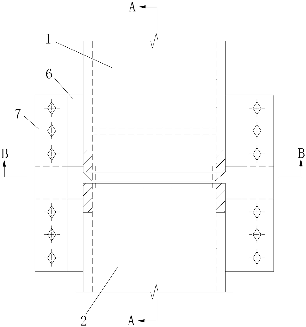
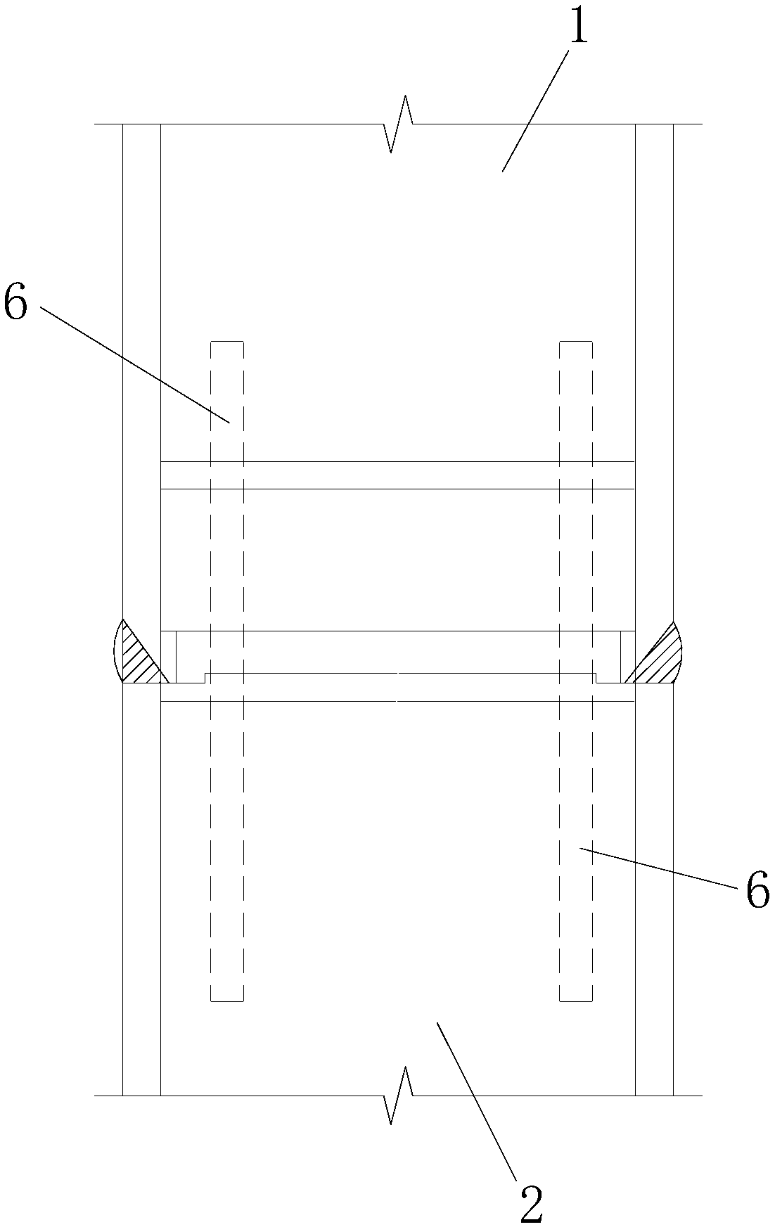
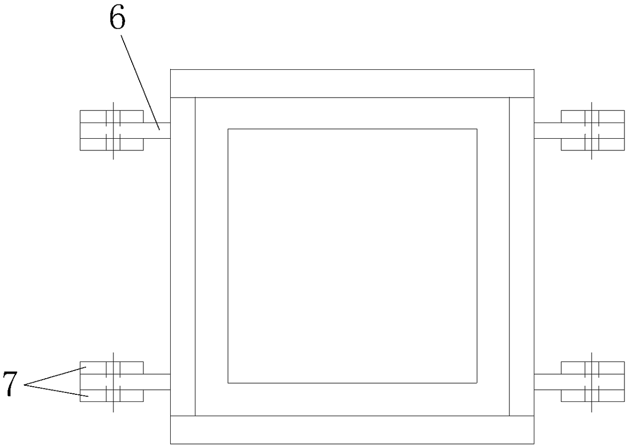
[0033] Such as Figure 4 to Figure 6 As shown, the box-shaped steel column splicing node of this embodiment includes an upper column unit 1 and a lower column unit 2, and a connection for connecting the upper column unit 1 and the lower column unit 2 is provided between the upper column unit 1 and the lower column unit 2 Unit 3, one end of the connection unit 3 is fixed to the end inner wall of the lower column unit 2, the other end of the connection unit 3 is higher than the lower column unit 2 and is connected to the end inner wall of the upper column unit 1 after the upper column unit 1 is docked and inserted Fixed. Specifically, the other end of the connection uni...


PUM


Abstract

The invention discloses a box-type steel column splice joint and further discloses a mounting method of the box-type steel column splice joint. The box-type steel column splice joint comprises an upper column unit and a lower column unit. A connecting unit used for connecting the upper column unit with the lower column unit is arranged between the upper column unit and the lower column unit, one end of the connecting unit is fixedly connected to the inner wall of the end of the lower column unit, and the other end of the connecting unit is higher than the lower column unit and is fixedly connected to the inner wall of the end of the upper column unit after butt joint and insertion of the upper column unit. The mounting method comprises the steps of prefabricating of the steel column units,hoisting of all the units, butt joint and temporary fixing, welding and the like. The box-type steel column splice joint and the mounting method thereof are suitable for super high-rise steel structure buildings and steel columns made of special steel, bearing special loads and high in safety level, and have the advantages that safety, economy and convenience are achieved, the splicing precisionis high, the strength is good, and the quality is excellent.

Description

technical field [0001] The invention belongs to the technical field of building structure engineering, and in particular relates to a splicing node of a box-shaped steel column and an installation method thereof. Background technique [0002] With the intensification of environmental pollution in our country, the strengthening of resource constraints, and the rising labor costs of the construction industry, the traditional labor-intensive construction industry is facing pressure to transform. Green buildings and construction industrialization have gradually become the development trend of the current construction industry. Steel structure buildings have the advantages of factory prefabrication, on-site installation, light-weight and high-strength materials, low transportation costs, and green, low-carbon, environmentally friendly and recyclable. They are the best carrier for building industrialization. [0003] Columns of super high-rise steel structure buildings and special...

Claims


Application Information

Patent Timeline
Patent Type & Authority Applications(China)
IPC IPC(8): E04B1/58E04B1/24
CPCE04B1/2403E04B2001/246
Inventor 杨灵冯先德许名志金军良
Owner ZHONGYE-CHANGTIAN INT ENG CO LTD
Why Eureka
Try Eureka