A 3D configuration stitching method for large components based on laser vision sensing

A large-scale component and visual sensing technology, applied in the direction of optical devices, measuring devices, instruments, etc., can solve the problems of difficult to achieve online measurement, poor anti-interference ability, heavy workload, etc., achieve fast speed, small stitching error, good accessibility

Active Publication Date: 2021-03-09
HARBIN INST OF TECH
View PDF14 Cites 0 Cited by
  • Summary
  • Abstract
  • Description
  • Claims
  • Application Information

AI Technical Summary

Problems solved by technology

[0012] The present invention aims to solve the problems of heavy workload, low efficiency, poor anti-interference ability, and difficulty in realizing online measurement of straightness of large and complex profiles, and proposes a new method—a large-scale component based on laser vision sensing The three-dimensional configuration stitching method, the method of the present invention adopts the self-designed straightness stitching algorithm, breaks through the length limit of a single measurement, and can be used for subsequent three-dimensional modeling, etc.

Method used


Image

  • A 3D configuration stitching method for large components based on laser vision sensing
  • A 3D configuration stitching method for large components based on laser vision sensing
  • A 3D configuration stitching method for large components based on laser vision sensing

Examples


specific Embodiment approach 1

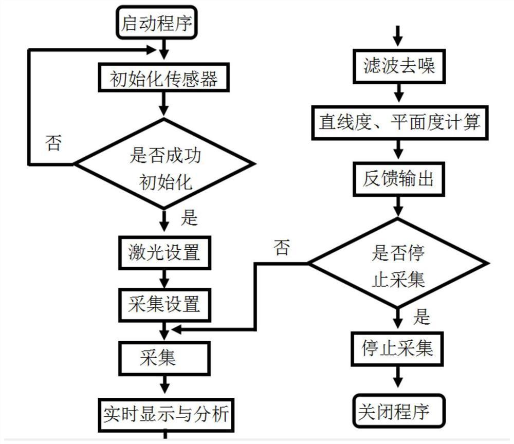
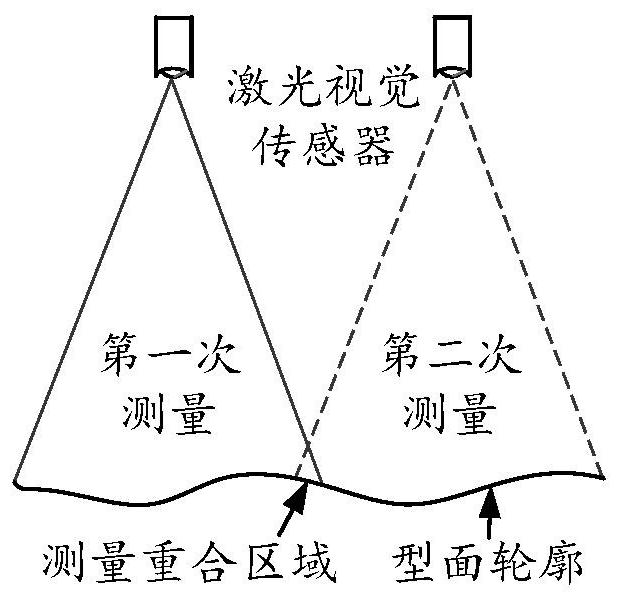
[0047] Specific embodiment one: a kind of large component three-dimensional configuration splicing method based on laser vision sensing of the present embodiment, it is carried out according to the following steps:

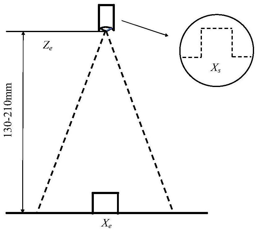
[0048] Step 1: Before measuring the contour of the profile, first calibrate the laser vision sensor, and restore the two-dimensional pixel image of the computer to the earth coordinates;

[0049] Step 2: Rigidly fix the laser vision sensor and the motion system to ensure that the sensor is always in the common working range during the motion process;

[0050] Step 3: Establish communication between the laser vision sensor and the PC controller, set sensor parameters, and set motion system parameters;

[0051] Step 4: The image scanning unit scans the profile image of the workpiece to be tested, and each scan obtains an array of 512 pixel points, the abscissa ranges from 0 to 511, the ordinate ranges from 0 to 1023, and the point array is in the abscissa Arranging...

specific Embodiment approach 2

[0070] Embodiment 2: This embodiment differs from Embodiment 1 in that the filtering algorithm is mean filtering, median filtering, Hamming filtering, quadratic filtering or bell-shaped filtering.

[0071] Others are the same as in the first embodiment.

specific Embodiment approach 3

[0072] Embodiment 3: The difference between this embodiment and Embodiment 1 is that the laser vision sensor is a linear laser sensor. Others are the same as in the first embodiment.


PUM


Abstract

A three-dimensional configuration splicing method for large components based on laser vision sensing, which involves the fields of image measurement and data processing. For the problem of online measurement, the invention adopts the self-designed straightness splicing algorithm, which breaks through the length limit of a single measurement and is used for subsequent three-dimensional modeling. The laser vision measurement method of the present invention is derived from the idea of ​​the pitch method, and uses the advantages of the accuracy, stability, and real-time performance of the short-distance measurement of the laser vision sensor to measure the straightness of large and complex profiles. Due to the large size of the large and complex profile, the profile can be divided into multiple overlapping sections with the same length as the laser stripes, and the segmented measurement is carried out in each segmented area, and then the data processing is carried out to splice and reassess the straightness curve. structure, calculate the straightness of large and complex surfaces by splicing and reconstructing straightness curves. The invention is applied to the field of image measurement.

Description

technical field [0001] The invention relates to the field of image measurement and data processing, in particular to a method for splicing three-dimensional configurations of large components based on laser vision sensing. Background technique [0002] With the vigorous development of intelligent manufacturing, people's requirements for the accuracy, measurement speed and non-contact of three-dimensional measurement technology and equipment are constantly increasing. Traditional measurement methods require a lot of labor, and it is difficult to meet the requirements of automatic and online measurement. For objects with complex shapes and large surface sizes, the operability of traditional measurement methods is significantly reduced, especially for online real-time measurement of large and complex surfaces. [0003] For large-size surface forming accuracy, accurate measurement of straightness is the most basic requirement. The straightness measurement methods commonly used...

Claims


Application Information

Patent Timeline
Patent Type & Authority Patents(China)
IPC IPC(8): G01B11/00G01B11/25G01B11/27
CPCG01B11/00G01B11/254G01B11/272
Inventor 雷正龙吴世博王志敏孙璐璐郭亨通黎炳蔚陈彦宾王智远
Owner HARBIN INST OF TECH
Why Eureka
Try Eureka