Surface treatment device of steel wire rope for elevator

A technology of surface treatment device and steel wire rope, applied in the field of elevator wire rope surface treatment device, can solve the problems of high labor rate, affecting the normal operation of steel wire rope, volatilization and the like

Inactive Publication Date: 2018-10-16
瑞普兰德电梯有限公司
View PDF0 Cites 7 Cited by
  • Summary
  • Abstract
  • Description
  • Claims
  • Application Information

AI Technical Summary

Problems solved by technology

[0002] The steel wire rope is used in the speed governor of the elevator and the traction main engine and other components, which requires the surface of the steel wire rope to be coated with lubricating oil to reduce the friction between the steel wire rope and other components in the elevator during the operation of the elevator, thereby increasing the service life of the elevator. However, most of the steel wire ropes sold by the manufacturers who produce steel wire ropes will store the steel wire ropes in the air for a long time due to stockpiling and other reasons. On the other hand, if the wire rope is exposed to the air for a long time, the lubricating oil on the surface of the wire rope may volatilize. Both of these situations will affect the normal operation of the wire rope. The performance of the elevator is tested, and the surface of the steel wire rope is treated at the same time to ensure that the steel wire rope can maintain the normal operation of the elevator. The general manual treatment will consume a lot of labor and the treatment effect is not high.

Method used


Image

  • Surface treatment device of steel wire rope for elevator
  • Surface treatment device of steel wire rope for elevator
  • Surface treatment device of steel wire rope for elevator

Examples


Embodiment Construction

[0029] The embodiment of the present invention will be described in detail in conjunction with the accompanying drawings. This embodiment is based on the technical solution of the present invention, and provides detailed implementation and specific operation process, but the scope of protection of the present invention is not limited to the following embodiments.

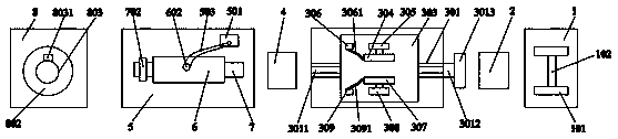
[0030] As shown in the accompanying drawings, the elevator steel wire rope surface treatment device is used to treat the surface of the steel wire rope. The pay-off mechanism, the detection structure 2, the cleaning mechanism, the drying mechanism 4, the oiling mechanism and the traction mechanism are arranged in sequence, and the pay-off mechanism includes a support frame 1 and two oppositely arranged supports Plate 101, installed on the two support plates 101 and used to place the rotating shaft 102 of the steel wire rope, the two support plates 101 are arranged above the support frame 1 along the vertical directio...


PUM


Abstract

The invention provides a surface treatment device of a steel wire rope for an elevator. The device comprises an unwinding mechanism, a detection structure, a cleaning mechanism, a drying mechanism, anoil applying mechanism and a traction mechanism, wherein the cleaning mechanism comprises a bottom plate, a moving assembly which is arranged on the bottom plate and cleaning assemblies which are arranged above the moving assembly, the cleaning assemblies include a cleaning assembly I and a cleaning assembly II, the cleaning assembly I comprises an air cylinder I, a brush plate I and a water tankI, the cleaning assembly II comprises an air cylinder II, a brush plate II and a water tank II, the oil applying mechanism comprises an oil receiving tray, an oil tank, a support rod and an oil applying assembly, the oil applying assembly comprises a support table and a hollow shaft which is used for putting the steel wire rope, the traction mechanism comprises a bracket, a traction motor, a rotary table and a reel, the traction motor is arranged on the bracket, the bottom end of the rotary table is connected with the output end of the motor, and the reel is arranged on the top surface of therotary table. According to the device, the surface of the steel wire rope can be cleaned, oil can be applied to the surface of the steel wire rope, manual labor is not consumed in the whole treatmentprocess, and the surface treatment effect of the steel wire rope is increased.

Description

technical field [0001] The invention relates to the technical field of elevator safety processing, in particular to an elevator wire rope surface treatment device. Background technique [0002] The steel wire rope is used in the speed governor of the elevator and the traction main engine and other components, which requires the surface of the steel wire rope to be coated with lubricating oil to reduce the friction between the steel wire rope and other components in the elevator during the operation of the elevator, thereby increasing the service life of the elevator. However, most of the steel wire ropes sold by the manufacturers who produce steel wire ropes will store the steel wire ropes in the air for a long time due to stockpiling and other reasons. On the other hand, if the wire rope is exposed to the air for a long time, the lubricating oil on the surface of the wire rope may volatilize. Both of these situations will affect the normal operation of the wire rope. The p...

Claims


Application Information

Patent Timeline
IPC IPC(8): B05C5/02B05C9/10B05C9/14B08B1/02B08B3/04B65H54/44
CPCB65H54/44B05C5/0241B05C9/10B05C9/14B08B3/041B65H2701/35B08B1/20B08B1/12
Inventor 王羽丁鹏王忠义邢文化
Owner 瑞普兰德电梯有限公司
Why Eureka
Try Eureka