
Engine thermal management system

A thermal management system and engine technology, applied in the cooling of engine components, machines/engines, engines, etc., can solve the problem of difficult to meet engine power, economy and emission requirements, poor heat transfer effect of oil cooler, single cooling Circuit and other issues to achieve the effect of optimizing engine performance, improving engine performance, and reducing exhaust temperature

Active Publication Date: 2018-10-12
ZHEJIANG GEELY HOLDING (GROUP) CO LTD +1
View PDF5 Cites 13 Cited by
  • Summary
  • Abstract
  • Description
  • Claims
  • Application Information

AI Technical Summary

Problems solved by technology

Generally, the traditional thermal management system is a single cooling circuit, which makes it difficult for the traditional thermal management system to meet the engine power, economy and emission requirements
The traditional thermal management system cools the cylinder block and the cylinder head at the same time, and the warm-up effect is poor
In addition, in the warm-up stage, the heat transfer effect of the oil cooler is poor, the temperature rises slowly, and the friction loss is large.

Method used


Image

  • Engine thermal management system

Examples


Embodiment Construction

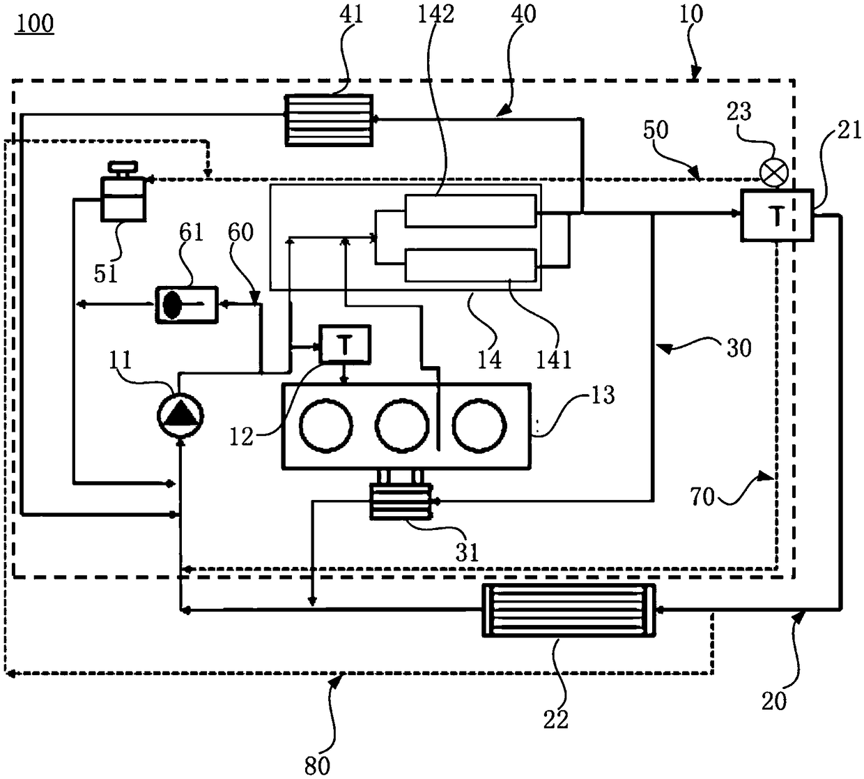
[0030] figure 1 is a schematic diagram of an engine thermal management system 100 according to one embodiment of the present invention. The engine thermal management system 100 of this embodiment may generally include a first circulating cooling circuit 10 and a second circulating cooling circuit 20 . Wherein, the first circulating cooling circuit 10 may include a mechanical water pump 11, a cylinder body valve 12, a cylinder body water jacket 13 and a cylinder head water jacket 14 connected in series by pipelines, wherein, before the cylinder body valve 12, the mechanical water pump 11 also It can be directly connected with the cylinder head water jacket 14 through pipelines, so that when the temperature of the coolant is lower than the first preset temperature, the cylinder block valve 12 is closed, and the coolant pumped from the mechanical water pump 11 directly enters the cylinder head water jacket 14 and Circulate back to the mechanical water pump 11. When the temperat...


PUM


Abstract

The invention provides an engine thermal management system and relates to the technical field of vehicle engines. The engine thermal management system comprises a first circulation cooling loop and asecond circulation cooling loop. The first circulation cooling loop comprises a mechanical water pump, a cylinder body valve, a cylinder body water jacket and a cylinder cover water jacket, wherein the mechanical water pump, the cylinder body valve, the cylinder body water jacket and the cylinder cover water jacket are connected in series though a pipeline. In front of the cylinder body valve, themechanical water pump is further directly connected with the cylinder cover water jacket through a pipeline. The second circulation cooling loop comprises a thermostat and a cooling device, wherein the thermostat and the cooling device are sequentially connected to the position behind the cylinder cover water jacket in series through a pipeline. The engine thermal management system is high in integration level and reasonable in arrangement; separated type cooling is adopted, and a cylinder cover is integrated with an exhaust manifold, so that rapid heating of an engine can be achieved; in thewarm-up period, engine oil is heated, friction is reduced, and overall vehicle heating demand is met; and high-temperature cooling of the engine oil, a supercharger and combustion high-temperature areas of a cylinder body and the cylinder cover is achieved, so that the performance of the engine is greatly improved, the oil consumption of the engine is lowered, and engine emission is optimized.

Description

technical field [0001] The invention relates to the technical field of vehicle engines, in particular to an engine thermal management system. Background technique [0002] With the continuous and in-depth research on vehicle technology, the performance requirements of vehicle engines are continuously improved, and the heat load of engines is also getting higher and higher. The thermal management system can manage and make the engine work at the best temperature, which can greatly reduce mechanical wear, increase the service life of the engine, and achieve the purpose of saving fuel. It can be seen that the thermal management system has a very important role in the normal operation of the engine. important role. Generally, the traditional thermal management system is a single cooling circuit, which makes it difficult for the traditional thermal management system to meet the engine power, economy and emission requirements. The traditional thermal management system cools the ...

Claims


Application Information

Patent Timeline
Patent Type & Authority Applications(China)
IPC IPC(8): F01P3/02F01P7/16F01M5/02
CPCF01M5/021F01P3/02F01P7/165F01P2003/027F01P2003/028
Inventor 高金恒尹建东王超何利孙晓阳沈源王瑞平
Owner ZHEJIANG GEELY HOLDING (GROUP) CO LTD
Learn More