Anti-seismic buffering method for steel structure for construction engineering

A technology of construction engineering and cushioning method, which is applied in the direction of building components, building structures, buildings, etc., and can solve the problem of unstable connection between support plates and support columns, inability to effectively alleviate the huge impact of earthquakes, and shorten the service life of steel structures, etc. problems, to achieve the effect of saving procurement costs, improving construction efficiency and construction quality, and improving product quality

Inactive Publication Date: 2018-10-12
曹菊平
View PDF1 Cites 1 Cited by
  • Summary
  • Abstract
  • Description
  • Claims
  • Application Information

AI Technical Summary

Problems solved by technology

Existing steel structures usually use supports as connecting members, and anti-seismic materials are arranged in the supports to improve the anti-seismic effect of the steel structure, and anti-seismic materials are mostly rubber pads or springs, which can only achieve a certain anti-seismic effect. , the vibration of the steel structure in the horizontal and vertical directions can easily damage the anti-seismic material, the anti-seismic effect is poor, and the steel structure is easily damaged, shortening the service life of the steel structure. In the prior art, for example, the invention patent with application number 201621417174.9 includes The steel structure leg, the bottom of the steel structure leg is connected with a support plate, the lower part of the support plate is connected with a support column, and also includes a shock absorbing base, the shock absorbing base is a groove with an opening upward, and the A first damping device is provided in the groove, and the first shock absorbing device includes a pressure-bearing rubber block fixed at the bottom of the groove. A through hole is provided in the middle of the pressure-bearing rubber block, and a first An elastic member, one end of the first elastic member is fixed on the groove bottom of the groove, and the other end is connected to the support column through the through hole, grooves are symmetrically arranged on the groove wall of the shock-absorbing base, and vertical A slide bar and a slide block that can slide on the slide bar are provided, the slide block is connected with the side wall of the support column through a second elastic member, and a friction plate is fixed on the opposite side of the slide block to the groove bottom of the groove, so The friction plate is in contact with the groove bottom of the groove. Although the invention has a simple structure, there are many deficiencies and defects. In the existing equipment, the design of the support plate and the support column has defects. In view of these situations, the design of the support plate and the support column The connection part is unstable, the first elastic member and the second elastic member cannot effectively relieve the huge impact force caused by the earthquake, and the support plate is easy to break at the connection part with the support column, which affects the service life of the steel structure. Only relying on the third The elastic part cannot drive the support plate to reset, and has a single function and large limitations, which reduces the use efficiency, increases the production cost of the enterprise, and causes a waste of steel structure resources. In order to avoid the above technical problems, it is indeed necessary to provide a construction steel Structural anti-seismic cushioning method to overcome the described defects in the prior art

Method used


Image

  • Anti-seismic buffering method for steel structure for construction engineering
  • Anti-seismic buffering method for steel structure for construction engineering
  • Anti-seismic buffering method for steel structure for construction engineering

Examples


Embodiment Construction

[0019] The following will clearly and completely describe the technical solutions in the embodiments of the present invention with reference to the accompanying drawings in the embodiments of the present invention. Obviously, the described embodiments are only some, not all, embodiments of the present invention. Based on the embodiments of the present invention, all other embodiments obtained by persons of ordinary skill in the art without making creative efforts belong to the protection scope of the present invention.

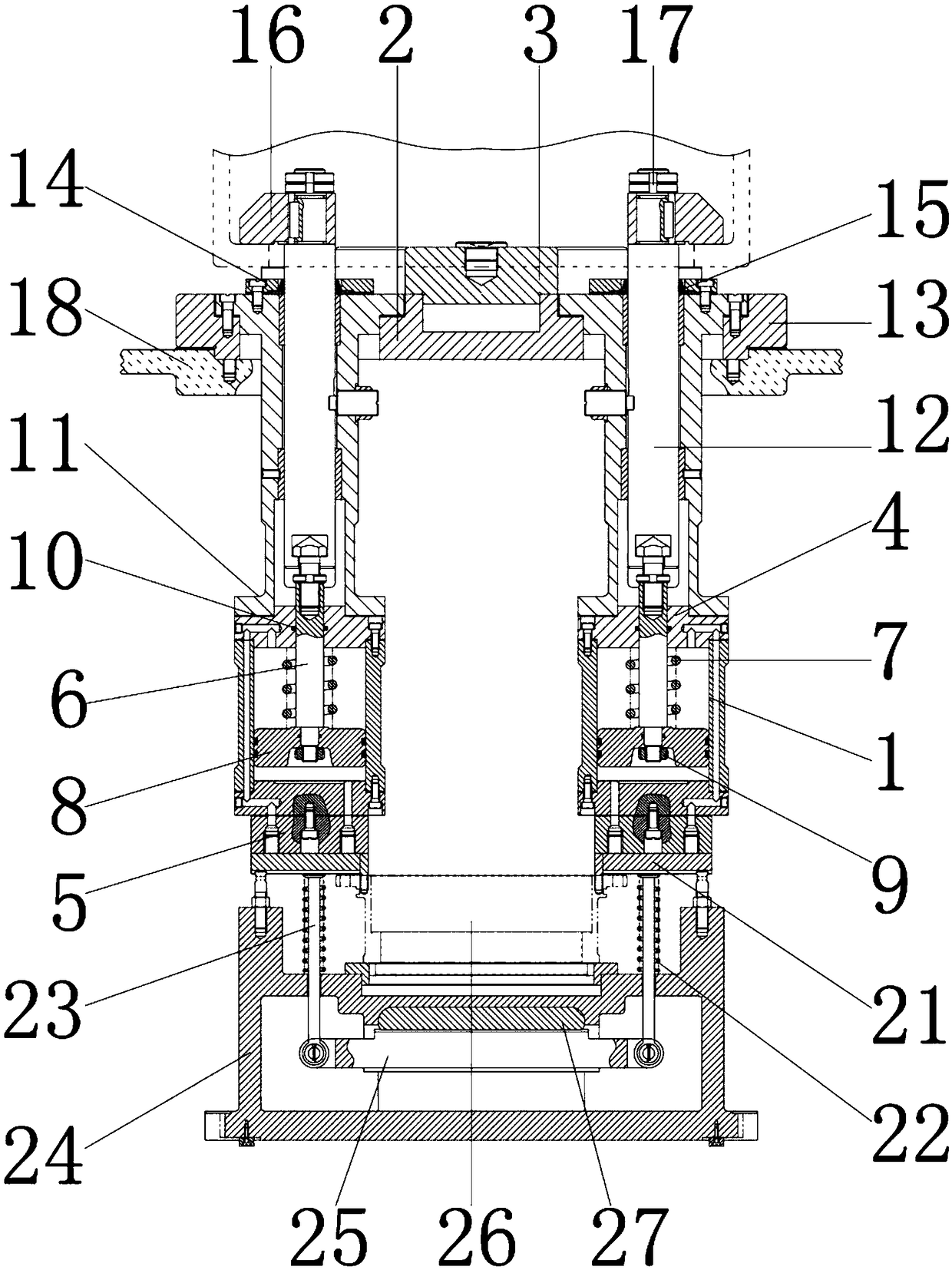
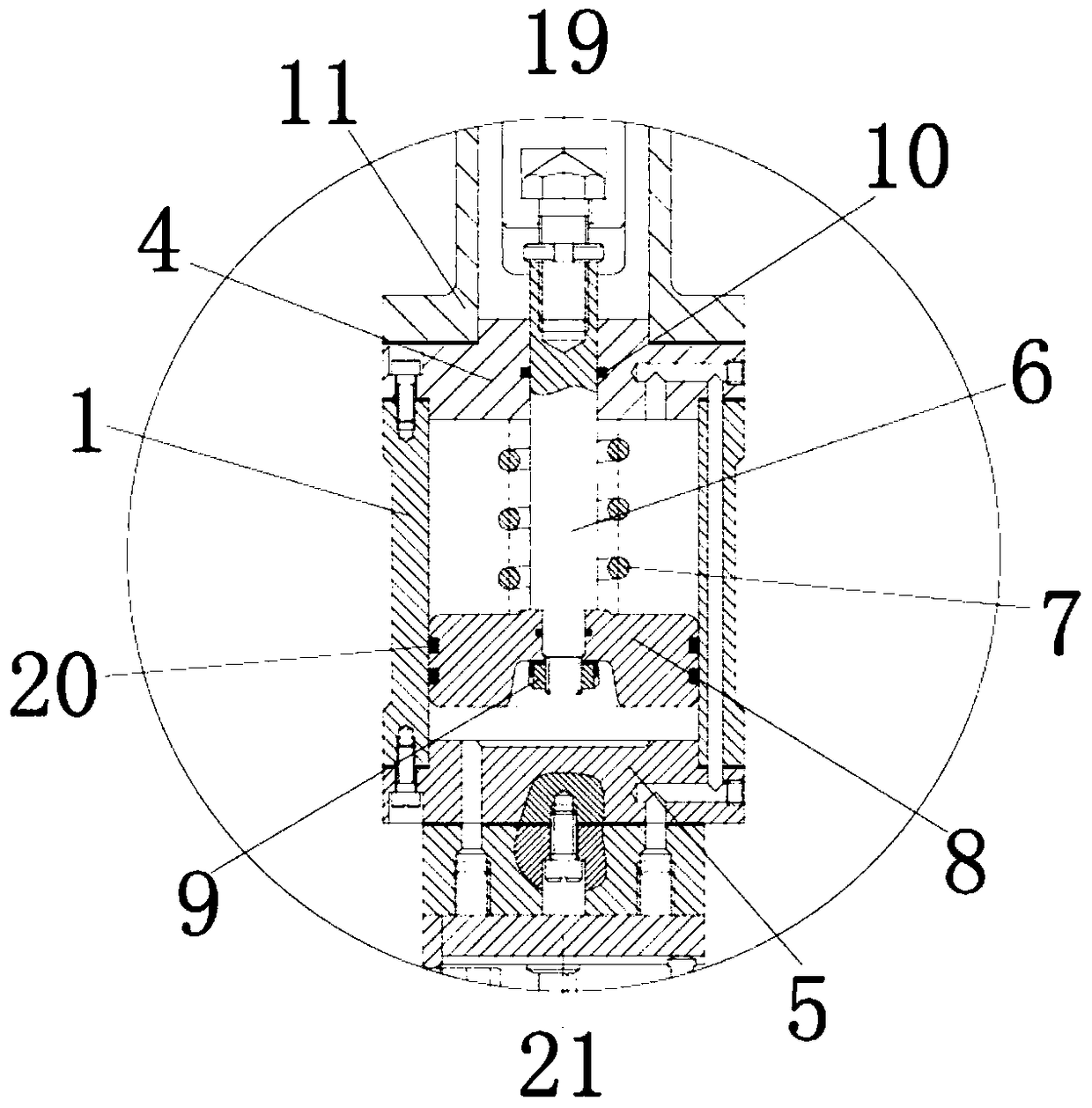
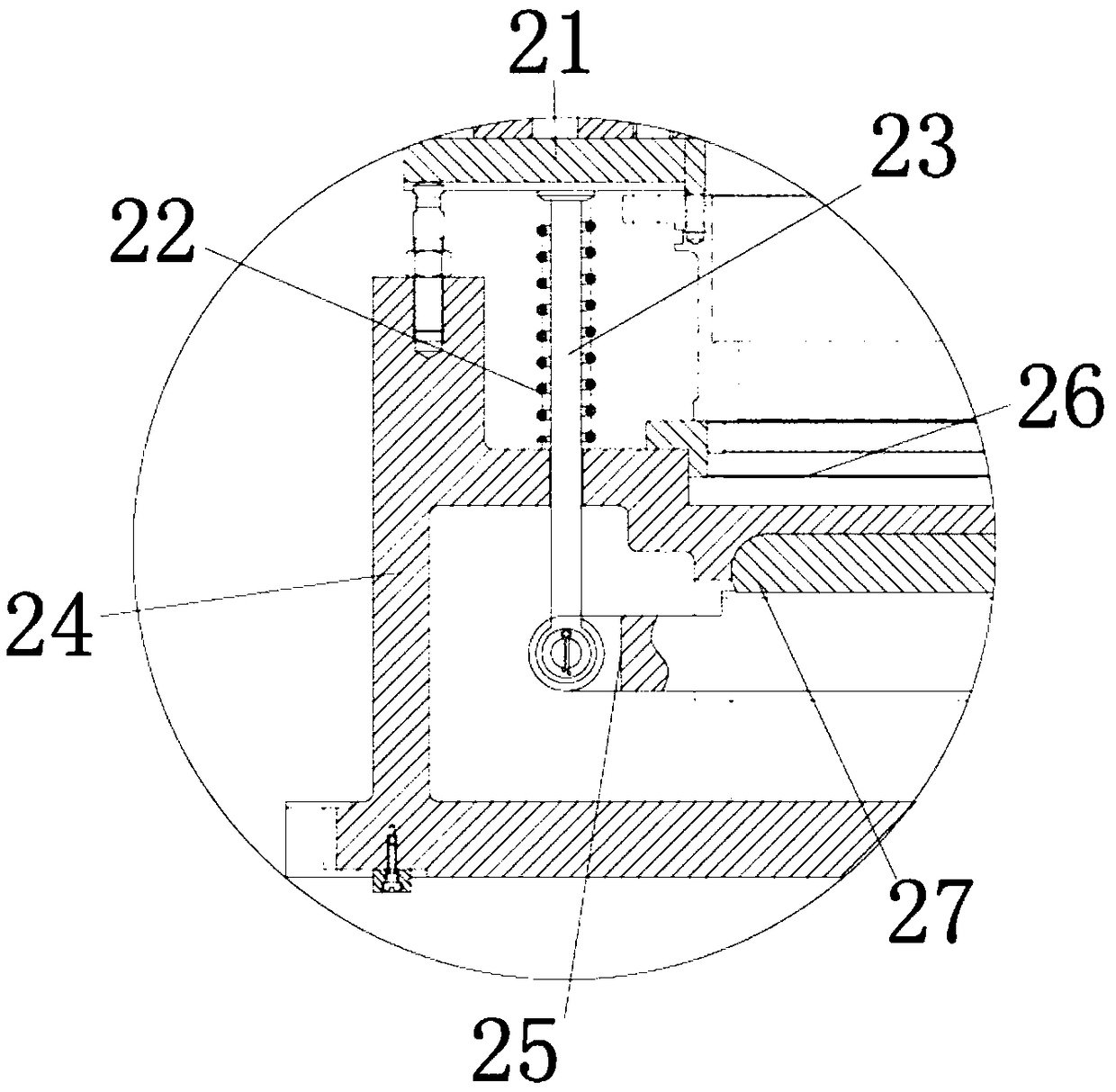
[0020] see Figure 1-3, the present invention provides a technical solution: a steel structure anti-seismic cushioning method for construction engineering, including a support 1 for installing and fixing a top plate 4 and a bottom plate 5, and a top plate 4 is installed on the top of the inner wall of the support 1 for fixing The central column 6, the outer wall of the top plate 4 is connected with the inner wall of the support 1, the inner wall of the top pla...


PUM


Abstract

The invention discloses an anti-seismic buffering method for a steel structure for construction engineering. The anti-seismic buffering method comprises supports, and top plates are installed at the top ends of the inner walls of the supports. The outer walls of the top plates are connected with the inner walls of the supports, and center columns are installed on the inner walls of the top plates.The outer walls of the center columns are connected with the inner walls of the top plates, and end caps are installed at the top ends of the center columns. The inner walls of the end caps are connected with the outer walls of the center columns, and first compression springs are installed on the outer walls of the center columns. According to the anti-seismic buffering method for the steel structure for construction engineering, through the cooperation of the supports, a clamping plate and a support plate, an existing anti-seismic buffering base of the steel structure for building engineering can be more recognized in the market, and the product quality of the anti-seismic buffering base of the steel structure for construction engineering is improved; and the procurement cost of construction enterprises is saved, and the waste of resources of the anti-seismic buffering base of the steel structure for construction engineering is avoided, and the anti-seismic buffering method for thesteel structure for construction engineering is suitable for popularization and application.

Description

technical field [0001] The invention relates to the technical field of steel structures for building construction, in particular to an anti-seismic buffering method for steel structures for building engineering. Background technique [0002] Steel structure is a structure composed of steel materials, which is one of the main types of building structures. The structure is mainly composed of steel beams, steel columns, steel trusses and other components made of section steel and steel plates. Welding seam, bolt or rivet connection, because of its light weight and easy construction, is widely used in large factories, stadiums, super high-rises and other fields. Earthquake is also called ground motion and ground vibration, which is caused by the rapid release of energy from the crust. During this period, a natural phenomenon of seismic waves will be generated. The plates on the earth will squeeze and collide with each other, causing the edge of the plates and the interior of the...

Claims


Application Information

Patent Timeline
Patent Type & Authority Applications(China)
IPC IPC(8): E04H9/02E04B1/36E04B1/98
CPCE04H9/021E04B1/36
Inventor 曹菊平
Owner 曹菊平
Why Eureka
Try Eureka