
Cutting tool for steering wheel ring

A steering wheel and tooling technology, applied in positioning devices, clamping devices, manufacturing tools, etc., can solve the problems of employees' physical and mental health, increased energy consumption and cost, and high labor intensity, so as to improve the production and working environment and reduce energy consumption and cost, the effect of reducing labor intensity

Inactive Publication Date: 2018-10-12
十堰皓凡工贸有限公司
View PDF0 Cites 2 Cited by
  • Summary
  • Abstract
  • Description
  • Claims
  • Application Information

AI Technical Summary

Problems solved by technology

[0005] In order to solve the above technical problems, the present invention provides a tool for cutting the spokes of the steering wheel to solve the problem that the existing method of cutting with a grinder not only consumes the grinding wheel, increases energy consumption and cost, but also causes great environmental pollution to the factory. The physical and mental health of employees is greatly affected, the labor intensity is high, and the production efficiency is low. Therefore, it is urgent to change the production method, and the ring winding machine is affected by the material of the raw material, the heat treatment method of the delivery state, and the thickness of the batch. It is difficult to control the size of the diameter of the spiral tube, and the stability of the cut-off size of the spoke is poor. It cannot be realized without auxiliary tooling on ordinary sawing machines. For this reason, an axial pressure and external expansion tooling is required.

Method used


Image

  • Cutting tool for steering wheel ring
  • Cutting tool for steering wheel ring
  • Cutting tool for steering wheel ring

Examples


Embodiment

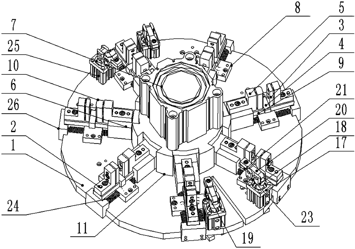
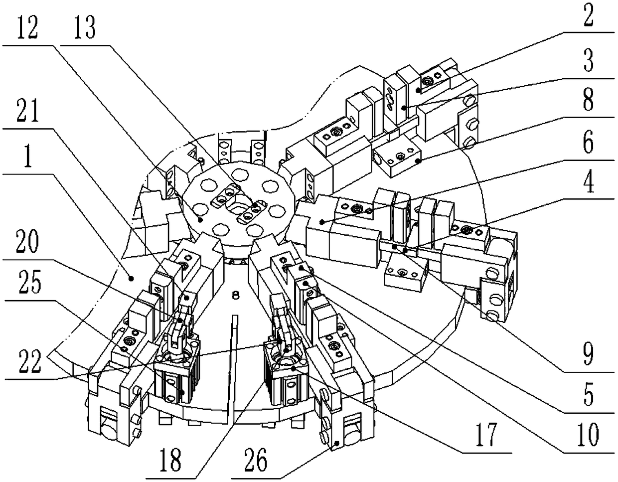
[0025] as attached figure 1 to attach Figure 4 Shown: a tool for cutting the spokes of a steering wheel, including a base plate 1, a first connecting block 2, a first limiting block 3, a cushion block 4, a second connecting block 5, a slider 6, a compression cylinder 7, and a return spring Limit 8, slide rail 9, second limit block 10, cylinder support 11, inclined wedge body 12, anti-rotation pressure block 13, first fixed support 14, second fixed support 15, third fixed support 16, support 17, gas rod end connection 18, connecting plate 19, pressing arm 20, pressing block 21, pin shaft 22, spacer 23, return spring 24, clamping cylinder 25 and end block 26; base plate 1 is a disc structure, with a stepped hole in the middle; the first connecting block 2 is fixed on the slide rail 9 through bolt connection, the first limit block 3 is fixed on the inner side of the first connecting block 2 through bolt connection; the second connecting block 5 is connected through bolt Fixed ...


PUM


Abstract

The invention provides a cutting tool for a steering wheel ring. The cutting tool comprises a clamping cylinder and an end block; a bottom plate is of a disc structure and a step hole is formed in themiddle of the bottom plate; a first connection block is fixed to a sliding rail in a bolt connection mode, and a first limiting block is fixed to the inner side of the first connection block in a bolt connection mode; a second connection block is fixed to the top side of a sliding block in a bolt connection mode; a cylinder support is fixed to the top side of the bottom late in a bolt connectionmode; the clamping cylinder is connected to the top end of the cylinder support through bolts; and the sliding rail is arranged on the top side face of the end block, protrudes out towards the circlecenter of the bottom plate and is arranged on the bottom side of the sliding block. The cutting tool is convenient to operate, efficient in production and attractive in appearance, the dimension stability of the ring in the cutting process can be ensured, precision is improved to + / -0.5 mm, meanwhile, the phenomenon like a high degree of pollution in the cutting process of an abrasive wheel is avoided, the production work environment is greatly improved for workers in a workshop, the labor intensity of the workers is relieved, and energy consumption and cost are reduced.

Description

technical field [0001] The invention belongs to the technical field of security components, and more specifically relates to a steering wheel spoke ring cutting tool. Background technique [0002] The traditional processing method of the steering wheel spoke ring is to roll a certain length of seamless steel pipe with a pipe coil machine into a helical spiral pipe that can be finally cut into more than three closed round pipes, and then use a grinder to cut it radially. Three closed round tubes are formed, and the two cut joints are welded to form spoke rings. [0003] Based on the above, the inventors found that this method of cutting with a grinder not only consumes the grinding wheel, increases energy consumption and cost, but also causes a lot of environmental pollution to the factory, which has a great impact on the physical and mental health of employees, and the labor intensity is high. , the production efficiency is low, so it is urgent to change the production meth...

Claims


Application Information

Patent Timeline
IPC IPC(8): B23Q3/08
CPCB23Q3/08B23Q3/062B23Q2703/04
Inventor 罗高翔张贵华李坤朱军章付金周辉瞿伟王选和
Owner 十堰皓凡工贸有限公司
Learn More