
Round steel surface imaging regulating device and method

A technology for adjusting devices and round steel, which is applied in the direction of measuring devices, optical testing flaws/defects, instruments, etc., can solve the problems of high steel shape requirements, inability to use round steel detection, high shape requirements, etc., to improve stability and The accuracy of the position, the ability to improve the finish and the ability to resist the influence of high temperature radiation, and the effect of convenient operation

Active Publication Date: 2018-10-09
HUAZHONG UNIV OF SCI & TECH
View PDF8 Cites 10 Cited by
  • Summary
  • Abstract
  • Description
  • Claims
  • Application Information

AI Technical Summary

Problems solved by technology

[0004] One is a substrate surface detection method and equipment disclosed in CN1568419A, the core of which is to provide a reflection image of at least one target above the surface, which is detected by digital processing of local phases along two directions. The digital processing is used to calculate the local slope changes and then deduce the surface curvature changes or height changes according to these changes. This method can only be used for the detection of conventional slabs, and is not suitable for the detection of round steel;
[0005] The second is a strip surface detection method and device disclosed in CN1508535A. The method is mainly used together with a panoramic camera and a high-resolution scanning camera. The movable scanning camera scans and enlarges the detection of the local area, which can not only detect the more obvious defects, but also detect the smaller surface defects of continuous production, so as to improve the accuracy of the detection of strip surface defects. The result of the whole device is simple, But it is not suitable for testing round steel;
[0006] The third is a surface detection device and surface detection method disclosed in CN1696672A, which mainly includes an irradiation unit that irradiates light onto the surface, and a detection unit that detects the intensity of the reflected light on the surface. The method mainly judges the surface quality by detecting the intensity of the reflected light , this method has high requirements on the shape of the steel and can only be used for the detection of conventional slabs;
[0007] The fourth is a surface detection device disclosed in CN1892202A and a surface detection method using the detection device. The device mainly includes a transfer rod that is isolated from the detection surface of the detection object and has a light-emitting part and a light-receiving part that are respectively combined at both ends of the transfer rod. The optical sensor of the part, and the light sensor used to send and receive light in a direction parallel to the detection surface of the detection object at a predetermined distance from the detection surface of the detection object, the driving part and the position adjustment part, etc., the device can detect the upper surface or bottom surface of the substrate impurities, but it has high requirements on shape, so it cannot be used for round steel detection
[0008] In summary, there is currently no technology that can effectively solve the problem of round steel surface detection and imaging.

Method used


Image

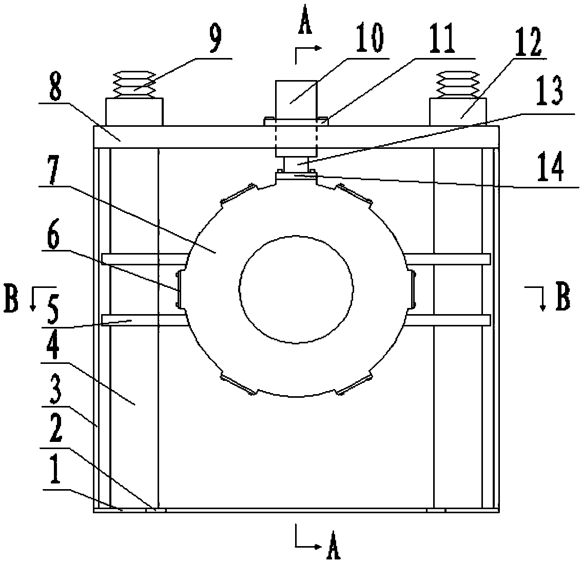
  • Round steel surface imaging regulating device and method
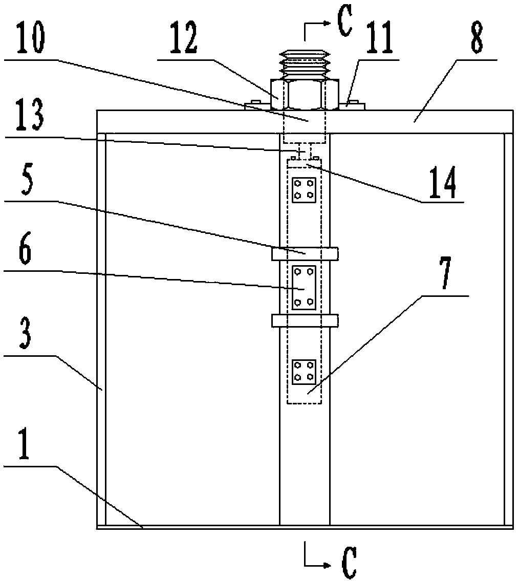
  • Round steel surface imaging regulating device and method
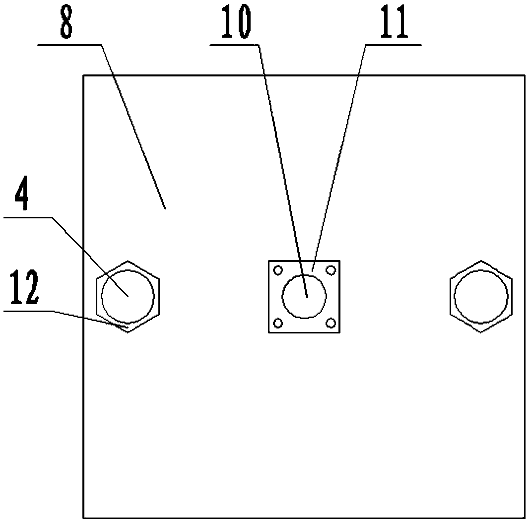
  • Round steel surface imaging regulating device and method

Examples


Embodiment Construction

[0043]In order to make the objectives, technical solutions and advantages of the present invention clearer, the present invention will be further described in detail below with reference to the accompanying drawings and embodiments. It should be understood that the specific embodiments described herein are only used to explain the present invention, but not to limit the present invention. In addition, the technical features involved in the various embodiments of the present invention described below can be combined with each other as long as they do not conflict with each other.

[0044] The basic idea of ​​the invention is as follows: since the cross-section of the wire rod and the bar is circular, multiple sets of cameras must be used to photograph the surface quality of the round steel in the circumferential direction, so that the product quality can be comprehensively judged. There are various sizes (the rolling diameter of wire rods, bars, etc. can be selected according t...


PUM


Abstract

The invention belongs to the technical field of imaging regulation, and particularly discloses a round steel surface imaging regulating device. The round steel surface imaging regulating device comprises a support module, a regulation module and an imaging module, wherein the support module comprises a bottom plate, a top plate and support plates; wherein the top plate is arranged above the bottomplate; the support plates are connected with the bottom plate and the top plate; upright posts are also arranged between the bottom plate and the top plate; the regulation module comprises an ascending and descending oil cylinder; the ascending and descending oil cylinder are fixed on the top plate; a first displacement sensor is arranged at the inside; a positioning lug boss is arranged under apiston rod of the ascending and descending oil cylinder; the imaging module comprises an installing frame and a plurality of imaging units; the installing frame is arranged under the positioning lug boss and is arranged on a guide plate; the axial line is parallel to the horizontal plane; the guide plate is sleeved on the upright posts; a plurality of guide grooves in annular distribution are formed in a cylinder; the plurality of imaging units are sequentially inserted into the corresponding guide grooves and face a round steel to be tested inside the hollow cylinder. The real-time high-precision regulation of the height of a plurality of cameras and the distance away from the round steel surface can be realized; the advantages of simple structure, operation convenience and the like are realized.

Description

technical field [0001] The invention belongs to the technical field of imaging adjustment, and more particularly, relates to an imaging adjustment device and method for the surface of a round steel. Background technique [0002] With the development of the market economy, the requirements for product quality continue to increase, and it is particularly important to quickly test products online. For steel products, CCD cameras are mostly used to quickly scan and image the appearance of steel products online, and compare and identify with the map in the standard library to judge the quality of the product. At present, many iron and steel enterprises have successfully developed on-line detection systems for the surface quality of steel products with regular shapes, such as continuous casting billet surface quality on-line detection systems, strip surface quality on-line detection systems, etc. However, due to the circular section of round steel, It is necessary to place multip...

Claims


Application Information

Patent Timeline
Patent Type & Authority Applications(China)
IPC IPC(8): G01N21/88G01N21/952G01N21/01G01N21/15
Inventor 高亮严旭果
Owner HUAZHONG UNIV OF SCI & TECH
Learn More