Eureka AIR delivers breakthrough ideas for toughest innovation challenges, trusted by R&D personnel around the world.

A system and method for cleaning in-furnace waste materials during major overhaul of a large blast furnace

A waste and blast furnace technology, applied in the field of blast furnaces in ironmaking, can solve the problems of labor-intensive manual cleaning, damage and deformation of the furnace shell, and inability to restore the original state, and achieves the goal of shortening cleaning construction time, improving material cleaning progress, and improving work efficiency. Effect

Pending Publication Date: 2018-10-09
BENGANG STEEL PLATES
View PDF6 Cites 2 Cited by
  • Summary
  • Abstract
  • Description
  • Claims
  • Application Information

AI Technical Summary

Problems solved by technology

[0004] In order to solve the above technical problems, the present invention provides a large-scale blast furnace overhaul furnace waste cleaning system and cleaning method, through the analysis and demonstration of the furnace body structure of the entire blast furnace, the excavator is used to lift the blast furnace into the furnace, and the mechanical Construction replaces manual work to quickly clean up the waste in the furnace, and an electric roller belt conveyor is added to reverse the transportation, so as to solve the problems in the prior art that the furnace shell is damaged and deformed and cannot be restored to its original state, manual cleaning is labor-intensive, and cleaning time is long.

Method used


Image

  • A system and method for cleaning in-furnace waste materials during major overhaul of a large blast furnace

Examples


Embodiment Construction

[0023] In order to make the object, technical solution and advantages of the present invention clearer, the present invention will be further described in detail below in conjunction with the accompanying drawings and embodiments. It should be understood that the specific embodiments described here are only used to explain the present invention, not to limit the present invention.

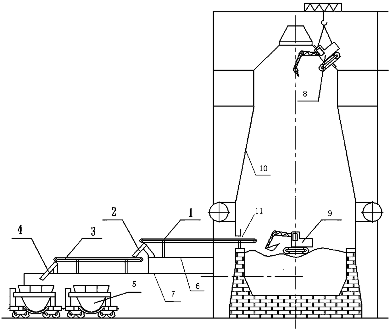
[0024] refer to figure 1 , the present invention provides a waste cleaning system in a large-scale blast furnace overhaul furnace, comprising a drum belt conveyor A1, a nozzle A2, a drum belt conveyor B3, a nozzle B4 and a slag tank 5, and the drum belt conveyor A1 is arranged on the tuyere platform 6, and one end It extends into blast furnace air supply port 7, and the bottom of the other end is in contact with the top of nozzle A2. The drum belt conveyor B3 is set on the platform of the cast iron plant. The lower end of nozzle A2 is in contact with the top of one end of drum belt conveyor B3. Th...


PUM

PropertyMeasurementUnit
widthaaaaaaaaaa

Abstract

The invention belongs to the field of blast furnaces in iron making, and particularly relates to a system and method for cleaning in-furnace waste materials during major overhaul of a large blast furnace. The system includes excavators, roller belt conveyors, spouts and slag receivers. The two excavators are lifted into the furnace from a top manhole, one of the excavators is provided with a hydraulic hammer and used for crushing waste materials, and the other excavator is provided with a bucket shovel and used for loading and transporting the waste materials. One of the roller belt conveyorsis arranged on a blast furnace tuyere platform, and the front end of the roller belt conveyor extends into the furnace from a blast furnace air supply port. A blast furnace cast house platform is provided with the other roller belt conveyor the front end of which is connected to the tail end of the roller belt conveyor on the blast furnace tuyere platform through a spout, and the tail end of whichis connected to the slag receivers on the ground through a spout. The waste materials in the furnace are conveyed through the excavators, the roller belt conveyors, and the spouts, from the blast furnace air supply port to the ground slag receivers, while passing through the tuyere platform and the cast house platform, and therefore manual work is replaced by mechanical operation, the working efficiency is greatly increased, in-furnace waste material cleaning time during major overhaul of the blast furnace roller is effectively shortened, the construction cost is saved, and the blast furnacecan be used for production in advance.

Description

technical field [0001] The invention relates to the technical field of blast furnaces in ironmaking, and in particular provides a waste cleaning system and cleaning method in a large-scale blast furnace overhaul furnace. Background technique [0002] At present, when the known large-scale blast furnace is overhauled, there are two methods for cleaning the waste in the furnace. One is to partially cut the furnace shell by gas welding, remove part of the stave and refractory bricks in the furnace, and then remove the residual waste in the furnace by means of mechanical equipment. The iron clot and the waste are cleaned out of the furnace together, and finally the furnace shell is restored to its original shape, and the stave is installed and refractory bricks are built. This method can clean up waste faster, but the furnace shell cannot be restored to its original shape due to damage and deformation, the water pipes connected to the cooling wall are prone to deformation, crack...

Claims


Application Information

Patent Timeline
Patent Type & Authority Applications(China)
IPC IPC(8): C21B7/00
CPCC21B7/00Y02P10/20
Inventor 张守喜王长波王运国王世友邹德胜周江刘庆涛
Owner BENGANG STEEL PLATES
Why Eureka
Eureka Blog
Learn More