
Automatic-puncturing terminal crimping tin dipping machine

A technology of piercing terminals and tin-dipping machines, which is applied in the direction of connection, connection connection by deformation, needle tip/slotted plate contact used for penetrating insulated wire/cable core wire, etc., which can solve damage and low efficiency , continuous processing products, etc.

Pending Publication Date: 2018-10-02
傅炳荣
View PDF0 Cites 4 Cited by
  • Summary
  • Abstract
  • Description
  • Claims
  • Application Information

AI Technical Summary

Problems solved by technology

[0002] Electrical connectors play a pivotal role in electronic products. It is responsible for data transmission and signal transmission between electronic products. The connection between terminals and wires in electrical connectors is mainly welding, and the welding process is performed manually one by one. It is a waste of time to dip the terminal wire (that is, the wire) and connect it with the terminal; the efficiency is low, and the quality of the output cannot be guaranteed at the same time, and due to the manual operation, it is at the processing center, so the Exhaust smoke and gas will directly cause damage to the artificial body, causing various diseases over time
[0003] What's more, currently on the market, only wires and terminal connectors are manually placed into the jig for crimping, which has poor stability and low processing efficiency. The existing technology cannot break through the entire roll of wires and multiple terminal connectors. Automatic feeding continuous processing products

Method used


Image

  • Automatic-puncturing terminal crimping tin dipping machine
  • Automatic-puncturing terminal crimping tin dipping machine
  • Automatic-puncturing terminal crimping tin dipping machine

Examples


Embodiment Construction

[0030] Below in conjunction with accompanying drawing and embodiment of description, specific embodiment of the present invention is described in further detail:

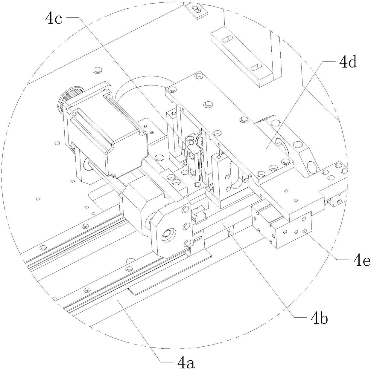
[0031] refer to Figure 1 to Figure 12 The shown automatic piercing type terminal crimping tin dipping machine includes a processing table 1, a terminal transfer device 2 arranged on the front side of the processing table 1, and tin dipping devices 7 arranged symmetrically at the left and right ends of the processing table 1 and clamping materials. Device 4, a crimping device 5 is provided above the processing table 1, the crimping device 5 is located between the tin dipping device 7 and the clamping device 4, a stabilizing block 6 is provided on the processing table 1, and the stabilizing block 6 is located in the crimping device 5 Right below, the top of the stabilizing block 6 is symmetrically equipped with a lower mold cutting knife seat 6a and a lower mold terminal avoiding block 6b, and a container for placing...


PUM


Abstract

An automatic-puncturing terminal crimping tin dipping machine comprises a processing table, a terminal transfer device, a tin dipping device and a clamping device, wherein the terminal transfer deviceis arranged at a front side of the processing table, the tin dipping device and the clamping device are arranged at a left end and a right end of the processing table, a crimping device is arranged on the processing table, a line arrangement rack module is arranged at an outer side of the processing table, a stabilization block is arranged on the processing table, a peeling and twisting knife holder module is arranged below the processing table, the stabilization block is arranged right below the crimping device, a lower die cutting knife holder and a lower die terminal avoidance block are symmetrically arranged at the top of the stabilization block, an accommodating cavity is formed between the lower die cutting knife holder and the lower die terminal avoidance block and is used for placing a terminal, a tin furnace is arranged below the tin dipping device, the tin dipping device comprises a limitation block, a plurality of line through pipes and a power assembly, the plurality of line through pipes are arranged at the top of the limitation block along a straight line, and the power assembly is used for driving the limitation block to move in a cross way. By the automatic-puncturing terminal crimping tin dipping machine, a terminal line can be automatically dipped with tin instead of manual operation and is crimped with the terminal, the efficiency is improved, and meanwhile,body harm to a worker brought by manual operation is prevented.

Description

technical field [0001] The invention relates to the field of terminal processing, in particular to an automatic piercing type terminal crimping tin dipping machine. Background technique [0002] Electrical connectors play a pivotal role in electronic products. It is responsible for data transmission and signal transmission between electronic products. The connection between terminals and wires in electrical connectors is mainly welding, and the welding process is performed manually one by one. It is a waste of time to dip the terminal wire (that is, the wire) and connect it with the terminal; the efficiency is low, and the quality of the output cannot be guaranteed at the same time, and due to the manual operation, it is at the processing center, so the Exhaust smoke and gas will directly cause damage to the artificial body, causing various diseases over time. [0003] What's more, currently on the market, only wires and terminal connectors are manually placed into the jig ...

Claims


Application Information

Patent Timeline
Patent Type & Authority Applications(China)
IPC IPC(8): H01R43/02H01R43/04H01R4/24
CPCH01R4/24H01R43/0235H01R43/04
Inventor 傅炳荣
Owner 傅炳荣
Learn More