Engine transmission hydraulic torque converter

A technology for hydraulic torque converters and gearboxes, which is applied in the direction of mechanical equipment, transmission devices, fluid transmission devices, etc. It can solve problems such as burrs and wear, poor oil flow, and easy formation of swirls, etc., to reduce Friction, increased device load, less prone to damage and cracking

Pending Publication Date: 2018-10-02
南京世界村汽车动力有限公司
View PDF0 Cites 0 Cited by
  • Summary
  • Abstract
  • Description
  • Claims
  • Application Information

AI Technical Summary

Problems solved by technology

[0002] The hydraulic torque converter is an impeller machine that relies on fluid kinetic energy to transmit power. It is widely used in automobiles, forklifts, construction machinery and other fields. The hydraulic torque converter is mainly composed of pump wheels, turbines and guide wheels, and is installed in the engine and gearbox. Among them, hydraulic oil is used as the working medium, which plays the role of torque transmission, speed change and clutch, so that the engine can achieve soft start, and can automatically adjust the output of power and speed according to the change of load. The existing hydraulic torque converter turbine is affected The force area is small, the thrust of the turbine is small, and the vortex is easily formed at the entrance of the force surface of the turbine blade, which makes the oil flow poor and the transmission efficiency low. The spring absorbs the torsional vibration force of the rotating parts, and the load on the spring is large, which is prone to burrs and wear. At the same time, the existing hydraulic torque converter will generate noise during operation, and the turbine and the guide wheel are easy to wear. Therefore, The present invention proposes an engine gearbox hydraulic torque converter to solve the problems existing in the prior art

Method used


Image

  • Engine transmission hydraulic torque converter
  • Engine transmission hydraulic torque converter
  • Engine transmission hydraulic torque converter

Examples


Embodiment Construction

[0018] In order to deepen the understanding of the present invention, the present invention will be further described below in conjunction with the examples, which are only used to explain the present invention, and do not constitute a limitation to the protection scope of the present invention.

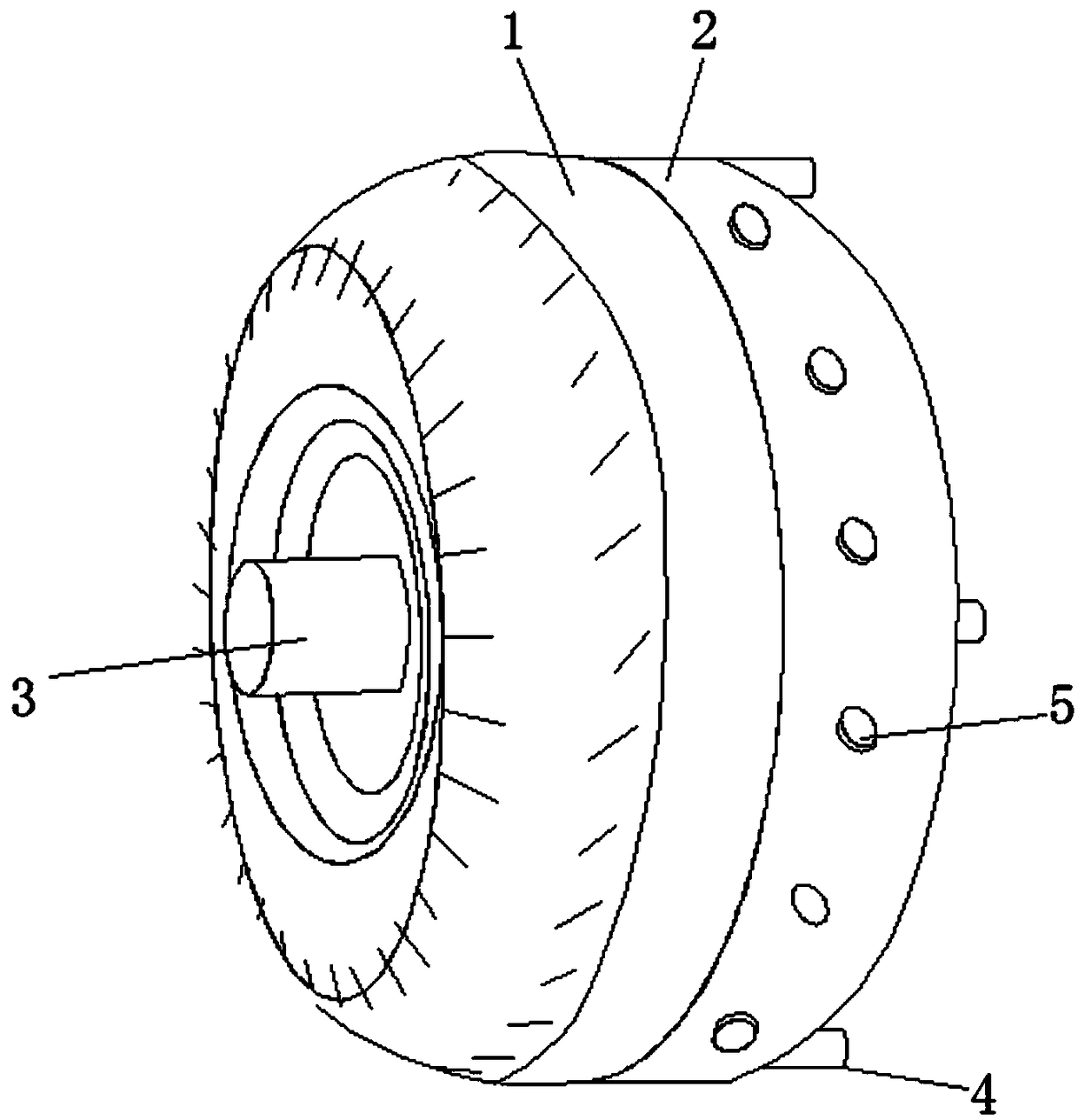
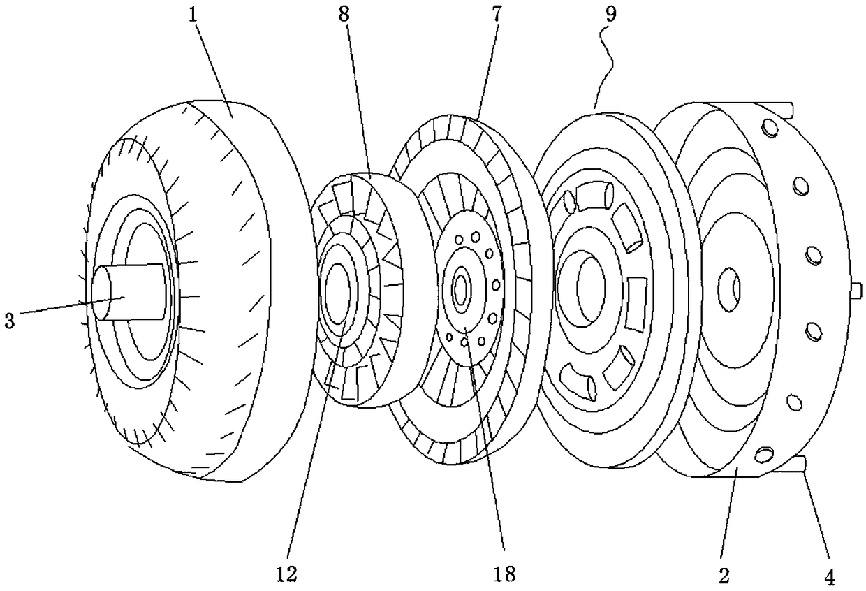
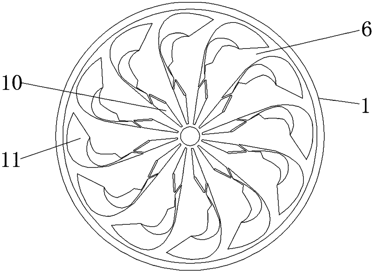
[0019] according to figure 1 , 2 , 3, 4, and 5, this embodiment provides a hydraulic torque converter for an engine gearbox, including a pump wheel housing 1 and a front housing cover 2, and a front housing cover is installed on one side of the pump wheel housing 1 2, and the drive interface 3 is provided at the middle position of the pump wheel housing 1 away from the side of the front housing cover 2, and the positioning bolt 4 is provided at the edge of the side of the front housing cover 2 away from the pump wheel housing 1, and the front housing cover 2 Install and fix the pump wheel housing 1 through the positioning bolts 4, the side wall of the front housing cover 2 is provid...


PUM


Abstract

The invention discloses an engine transmission hydraulic torque converter. The engine transmission hydraulic torque converter comprises a pump wheel shell and a front shell cover; the front shell cover is arranged on one side of the pump wheel shell, a drive connector is formed in the middle of the side, away from the front shell cover, of the pump wheel shell, a positioning bolt is arranged on the edge of the side, away from the pump wheel shell, of the front shell cover, the front shell cover and the pump wheel shell are fixedly mounted through the positioning bolt, reinforcing protrusions are arranged on the side wall of the front shell cover, a pump wheel is arranged in the pump wheel shell, a turbine, a guide wheel and a locking clutch assembly are arranged in the pump wheel shell andthe front shell cover, the turbine is arranged on one side of the pump wheel, and the guide wheel is arranged in the middle between the pump wheel and the turbine. Through segmented fit of pump wheelblades, stress area is increased, thrust borne by the turbine is improved, the backflow vortex is effectively avoided, the oil inflow speed of a turbine inlet can be increased, the oil flowing lossesare reduced, and transmission efficiency is improved.

Description

technical field [0001] The invention relates to the technical field of power transmission equipment, in particular to a hydraulic torque converter for an engine gearbox. Background technique [0002] The hydraulic torque converter is an impeller machine that relies on fluid kinetic energy to transmit power. It is widely used in automobiles, forklifts, construction machinery and other fields. The hydraulic torque converter is mainly composed of pump wheels, turbines and guide wheels, and is installed in the engine and gearbox. Among them, hydraulic oil is used as the working medium, which plays the role of torque transmission, speed change and clutch, so that the engine can achieve soft start, and can automatically adjust the output of power and speed according to the change of load. The existing hydraulic torque converter turbine is affected The force area is small, the thrust of the turbine is small, and the vortex is easily formed at the entrance of the force surface of th...

Claims


Application Information

Patent Timeline
Patent Type & Authority Applications(China)
IPC IPC(8): F16H41/04F16H41/24
CPCF16H41/04F16H41/24
Inventor 李健孙兰娟芮忠南周萌芳
Owner 南京世界村汽车动力有限公司
Why Eureka
Try Eureka