Sand control pipe for oil-sand separation in oil and gas exploitation

A technology for oil and gas exploitation and sand control pipes, which is applied in the field of separation of liquid-solid two-phase devices, can solve the problems of system permeability decrease, sand control time is short, and permeability is less than 40%, so as to speed up the inflow speed and keep sand The effect of good performance and high permeability

Active Publication Date: 2014-06-25
CHANGDE LYRUN MATERIAL
View PDF7 Cites 0 Cited by
  • Summary
  • Abstract
  • Description
  • Claims
  • Application Information

AI Technical Summary

Problems solved by technology

These screens are either expensive, or have a short sand control time, or are easily damaged, or have unsatisfactory sand control effects.
The quality and life of the sand control screen have a direct impact on the production and life of the oil and gas well. Once the sand control fails, it will affect the normal production of the oil and gas well, and even lead to the scrapping of the oil well.
Moreover, the filter materials used in these screens are almost all sintered and planar stainless steel metal meshes with several layers. Moreover, the clay attached to the mesh is not easy to flow out with the liquid, resulting in a sharp drop in the permeability of the system, which is less than 40%.

Method used


Image

  • Sand control pipe for oil-sand separation in oil and gas exploitation
  • Sand control pipe for oil-sand separation in oil and gas exploitation
  • Sand control pipe for oil-sand separation in oil and gas exploitation

Examples


Embodiment 1

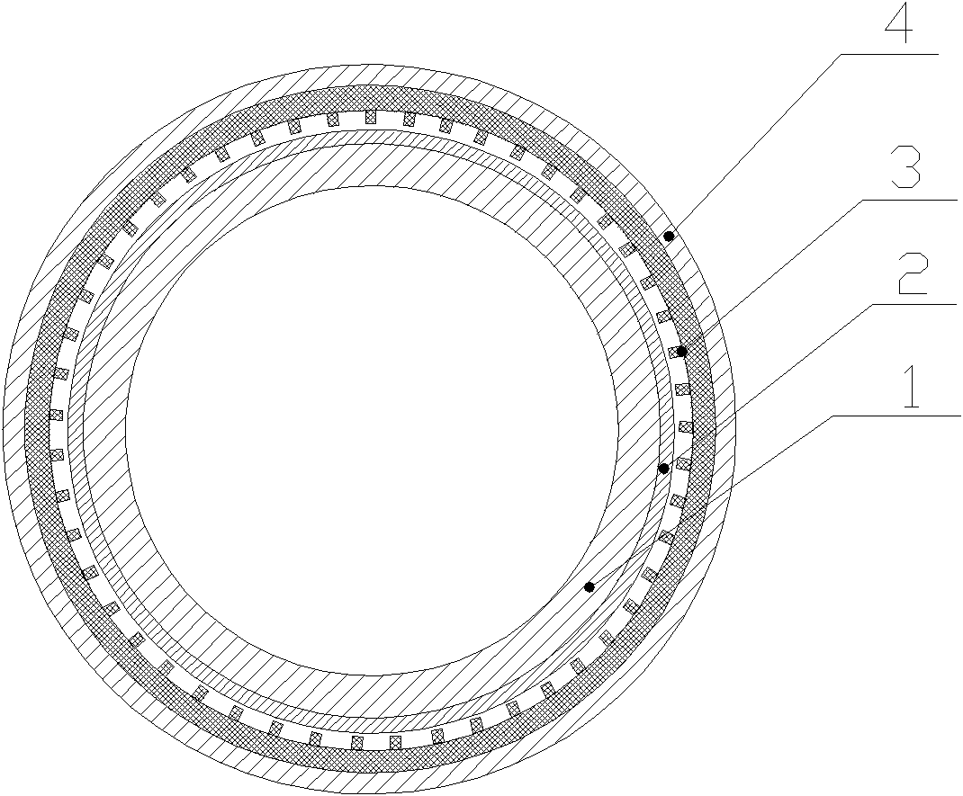
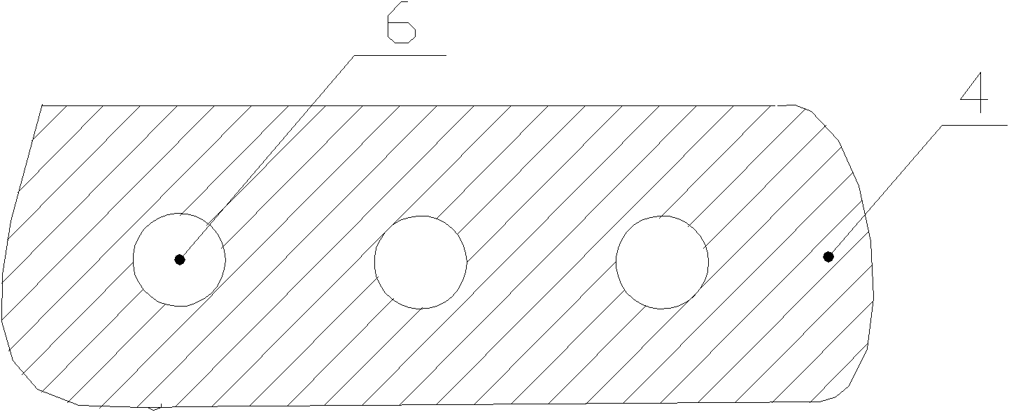
[0013] Such as figure 1 The sand control pipe shown is composed of a base pipe 1, an inner protective cover 2, a filter layer 3 and an outer protective cover 4 from the inside to the outside, wherein the inner protective cover, the filter layer and the outer protective cover are welded in sequence The sand control sleeve is fixed on the outside of the base pipe. Seepage holes are evenly distributed on the base pipe 1, such as figure 2 The shown outer protective cover 4 has several circular flow holes 6, and the inner protective cover 2 has the same flow holes.

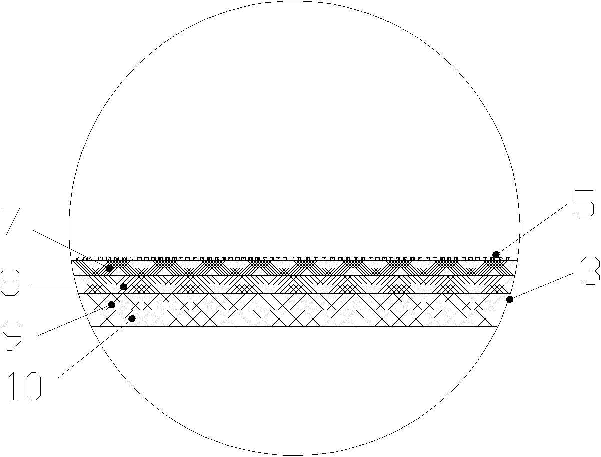
[0014] Take out the filter of the filter layer, such as image 3 As shown, the surface of the filter screen has uniform bumps 5, which are made of 4 layers of foamed nickel with different hole densities, and are made of foamed nickel 7, 8, 9 and 10 from the inside to the outside, and the innermost foamed nickel material 7. The hole density is 110PPI, the thickness is 2.0mm, and the bulk density of nickel metal is 1...

Embodiment 2

[0016] The sand control pipe is basically the same structure as in Example 1, except that the filter screen is different. Its surface is corrugated, and the filter screen is made of a foamed nickel-iron alloy material with a pore density of 95PPI and a thickness of 2.5mm. The bulk density of iron alloy is 2.0g / cm 3 .

Embodiment 3

[0018] Sand control pipe with basically the same structure as in Example 1, but the flow holes on the inner and outer protective covers of the sand control sleeve are square holes; the surface of the filter screen has uniform bumps, and is made of two layers of foam metal materials, and The layer is nickel foam with a pore density of 75PPI, a thickness of 3.0mm, and a bulk density of nickel metal of 2.0g / cm 3 ;The outer layer is foam nickel-iron alloy, its pore density is 55PPI, the thickness is 3.0mm, and the bulk density of nickel-iron alloy is 2.0g / cm 3 .


PUM


Abstract

The invention provides a sand control pipe for oil-sand separation in oil and gas exploitation. A sand control sleeve is fixed on a base pipe, seepage holes are evenly distributed on the base pipe, and an inner protective cover, a filter layer and an outer protective cover are welded together sequentially from the inside to the outside to form the sand control sleeve; the inner and the outer protective covers are respectively provided with a plurality of through holes; and the filter screen of the filter layer is made of one to four layers of foamed nickel or foamed nickel alloy. The sand control pipe has the advantages of good sand control effect, simple structure and technique, longer service life and low cost, and can effectively control sand in an oil well for a long time.

Description

technical field [0001] The invention relates to a device for separating liquid-solid two phases, in particular to a sand control pipe used for oil sand separation in oil and gas exploitation. Background technique [0002] During the development of oil and gas wells, formation sand will enter the wellbore with the flow of oil and gas, resulting in complex situations such as wellbore pump jamming and sand burial, affecting the normal production of oil and gas wells. Sand control screen is a mechanical filtering tool used to prevent formation sand from entering the wellbore and control formation sand production. At present, the screens used for mechanical sand control mainly include: pre-filled screens, wire-wrapped screens, metal fiber spun sand screens, slotted screens, etc. These screens either have a high cost, or have a short sand control time, or are easily damaged, or have an unsatisfactory sand control effect. The quality and life of the sand control screen have a dir...

Claims


Application Information

Patent Timeline
Patent Type & Authority Patents(China)
IPC IPC(8): E21B43/08E21B43/34
Inventor 邹超周永吴庆锋刘一李博
Owner CHANGDE LYRUN MATERIAL
Why Eureka
Try Eureka