
Multiphase flow hybrid conveying pipeline resistance reduction device and method of mine field

A drag reduction device and mixed transportation pipeline technology, which is applied in pipeline systems, mechanical equipment, gas/liquid distribution and storage, etc., can solve the problems of different mixed transportation components, large frictional resistance, and increased flow viscosity in oilfield blocks. Achieve the effects of reducing paraffin deposition, reducing the number of pigging times, and reducing flow resistance

Inactive Publication Date: 2013-06-19
SOUTHWEST PETROLEUM UNIV
View PDF8 Cites 0 Cited by
  • Summary
  • Abstract
  • Description
  • Claims
  • Application Information

AI Technical Summary

Problems solved by technology

However, the diameter of the mixed transportation pipeline is relatively large, and the mixed transportation components of each oilfield block are different, so the flow resistance is still relatively large
The current commonly used drag reduction method is mainly to add chemical drag reducers to the pipe to achieve the effect of drag reduction and viscosity reduction. However, most drag reducers have unstable performance and poor sustainability in the process of multi-phase mixed transportation. In addition, chemical drag reducers are toxic. , easy to pollute the environment, but also increase the difficulty of post-processing
[0003] In the case of crude oil with high wax content, high freezing point, and high viscosity, the friction resistance during transportation will be extremely large, which seriously affects the transportation efficiency. When the temperature drops to the wax precipitation point, the wax will gradually precipitate out, which not only increases the The energy consumption of the pipeline operation may also cause condensation accidents and affect the safe operation of the pipeline
When the mixed fluid is oil-water two-phase, an oil-water emulsion may be formed, which increases the flow viscosity, resulting in a serious drop in transmission efficiency
When the mixed fluid is mainly natural gas but contains a small amount of water phase, hydrates may form, causing blockage of pipelines, separation equipment and instruments

Method used


Image

  • Multiphase flow hybrid conveying pipeline resistance reduction device and method of mine field
  • Multiphase flow hybrid conveying pipeline resistance reduction device and method of mine field
  • Multiphase flow hybrid conveying pipeline resistance reduction device and method of mine field

Examples


Embodiment 1

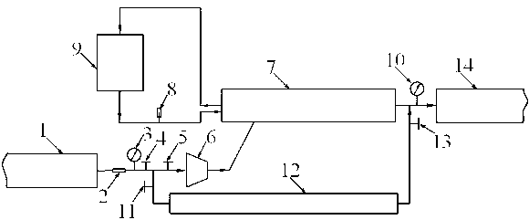
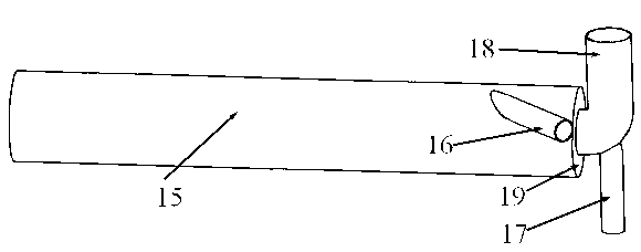
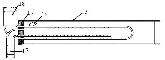
[0022] Example 1: When the fluid in the mixed transportation pipeline is oil-gas-water three-phase, the fluid flows into the reducer 6 from the upstream mixed transportation pipeline 1 through the flow meter 2, the pressure gauge 1 3, the valve 1 4 and the valve 2 5, and is accelerated by the tangential The inlet pipe 16 enters the device main body pipe 15 and forms a swirl in the annular space between the device main body pipe 15 and the hot water return pipe 18 . Due to the difference in density, the three phases of oil, gas and water form a stratified circulation in the pipeline 15 of the main body of the device. The water phase is close to the inner wall of the main pipe 15 of the device, avoiding the direct contact between the oil and the pipe wall, and greatly reducing the transportation resistance, while the gas phase is close to the hot water return pipe 18, and the oil phase is between the gas and water phases. Driven to move downstream. There is a hot water circulat...

Embodiment 2

[0023]Example 2: When the fluid in the mixed transportation pipeline is oil-water two-phase, the fluid flows into the reducer 6 from the upstream mixed transportation pipeline 1 through the flow meter 2, the pressure gauge 1 3, the valve 1 4 and the valve 2 5, and is accelerated by the tangential inlet The pipe 16 enters the device body pipe 15 and forms a swirl in the annular space between the device body pipe 15 and the hot water return pipe 18 . Due to the difference in density, the two phases of oil and water form a stratified circulation in the pipeline 15 of the main body of the device. The oil phase is close to the hot water return pipe 18, and the water phase is close to the inner wall of the main pipe 15 of the device, avoiding the direct contact between the oil and the pipe wall, and greatly reducing the transportation resistance. There is a hot water circulation system at one end of the oil-gas-water three-phase mixed-transport swirl drag reducing device 7, and wate...

Embodiment 3

[0024] Example 3: When the fluid in the mixed transportation pipeline is gas-water two-phase, the fluid flows from the upstream mixed transportation pipeline 1 through the flow meter 2, the pressure gauge 1 3, the valve 1 4 and the valve 2 5 into the reducer 6, and after acceleration, it flows from the tangential The inlet pipe 16 enters the device main body pipe 15 and forms a swirl in the annular space between the device main body pipe 15 and the hot water return pipe 18 . Due to the difference in density, the two phases of gas and water form a stratified circulation in the main pipe 15 of the device, the water phase is close to the inner wall of the main pipe 15 of the device, and the gas phase is close to the hot water return pipe 18 . There is a hot water circulation system at one end of the oil-gas-water three-phase mixed-transport swirl drag reducing device 7, and water flows in by the hot water inlet pipe 17 after being heated by the heating furnace 9, and flows out by ...


PUM


Abstract

The invention discloses a multiphase flow hybrid conveying pipeline resistance reduction device and a multiphase flow hybrid conveying pipeline resistance reduction method of a mine field. The multiphase flow hybrid conveying pipeline resistance reduction device and the multiphase flow hybrid conveying pipeline resistance reduction method are characterized in that: hybrid conveyed fluid is accelerated by a reducing pipe and then enters a device main body pipeline by a tangential inlet pipe; and an annular space between the device main body pipeline and a hot water reflow pipe forms a rotational flow. Due to different densities, oil phase, gas phase and water phase form layered circular flows in the device main body pipeline. The water phase is closely attached to the inner wall of the device main body pipeline, so that direct contact of oil with the pipe wall is avoided, and the conveying resistance is greatly reduced. The oil phase is positioned between the gas phase and the water phase and is driven by the gas phase and the water phase to be transferred towards downstream side. One end of the oil, gas and water three-phase hybrid conveying rotational flow resistance reduction device is connected with a hot water circulating system to heat the hybrid conveyed fluid, so that on one hand, the viscosity of crude oil in the hybrid conveyed pipe can be reduced, and on the other hand, gas can be expanded properly, and the air flow speed is increased. The multiphase flow hybrid conveying pipeline resistance reduction device and the multiphase flow hybrid conveying pipeline resistance reduction method have the advantages of adoption of a physical technology for resistance reduction, no toxicity, no pollution, low manufacturing cost, reliability in operation, good resistance reduction effect, capability of effectively preventing paraffin deposit and high promotion and application value.

Description

technical field [0001] The invention relates to a drag reduction device and method for a multiphase flow mixed transportation pipeline in a mine field by using physical technology to reduce resistance and increase transportation, and belongs to the field of oil and gas gathering and transportation. Background technique [0002] In order to save operating costs and reduce flow resistance to a certain extent, existing mine pipelines usually adopt the form of mixed transportation, which often presents oil-gas-water three-phase, oil-water two-phase or gas-water two-phase situation. However, the diameter of the mixed transportation pipeline is relatively large, and the mixed transportation components of each oilfield block are different, so the flow resistance is still relatively large. The current commonly used drag reduction method is mainly to add chemical drag reducers to the pipe to achieve the effect of drag reduction and viscosity reduction. However, most drag reducers hav...

Claims


Application Information

Patent Timeline
Patent Type & Authority Patents(China)
IPC IPC(8): F17D1/18F17D3/01
Inventor 朱红钧林元华郑云萍马国光戚兴冯光敬加强王其军
Owner SOUTHWEST PETROLEUM UNIV
Learn More