
Method and device for simulating generation of S-mode baseband signal

A baseband signal and mode technology, applied in radio wave measurement systems, instruments, etc., can solve problems such as the inability to effectively verify the S mode signal, and achieve the real effect of the S mode baseband signal

Pending Publication Date: 2018-09-28
四川省安道速博科技有限公司
View PDF0 Cites 3 Cited by
  • Summary
  • Abstract
  • Description
  • Claims
  • Application Information

AI Technical Summary

Problems solved by technology

[0003] In order to solve the problem that the S-mode transponder in the prior art cannot effectively verify the S-mode signal in the factory test and field test, a method and device for simulating the S-mode baseband signal generation are provided

Method used


Image

  • Method and device for simulating generation of S-mode baseband signal
  • Method and device for simulating generation of S-mode baseband signal
  • Method and device for simulating generation of S-mode baseband signal

Examples


Embodiment 1

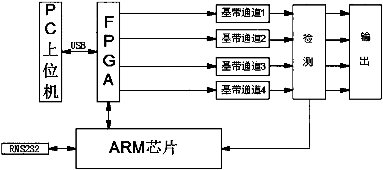
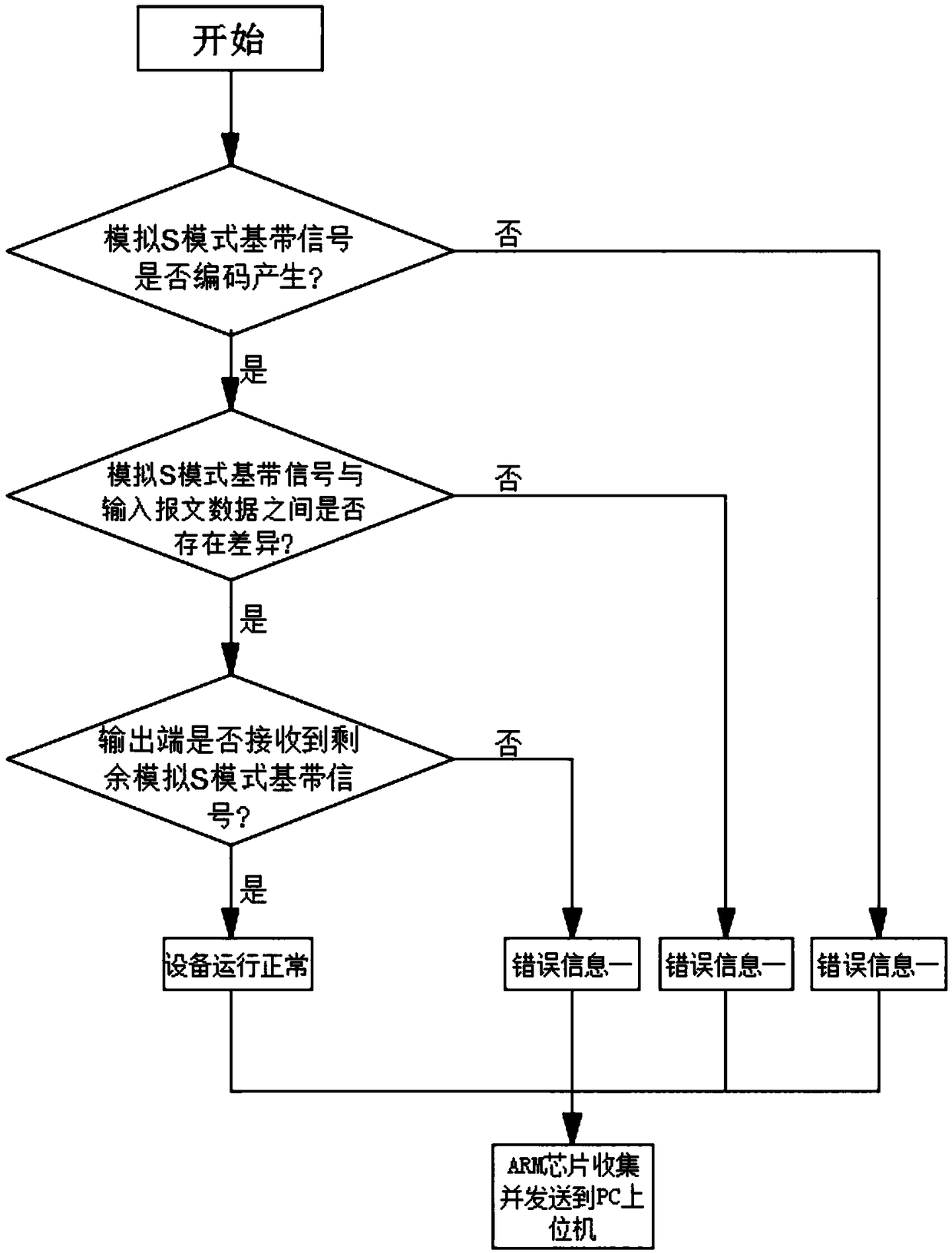
[0043] refer to figure 1 and 3 , a device for simulating S-mode baseband signal generation, comprising:

[0044] The power supply module is used to convert the power supply of the device from AC 220V to each group of low-voltage DC power supplies required in the equipment, and can complete the collection and transmission of status information through the BIT monitoring of the power supply system;

[0045] USB2.0 interface, as an auxiliary communication interface. The purpose of using USB2.0 communication is to avoid the use of network and other means of communication. It is necessary to configure the parameters such as the IP of the computer. The use requires a high level of computer knowledge for the operator, and when the computer network port is occupied, the device cannot be used at the same time. At present, the computer provides multiple sets of USB communication ports, which can ensure that the device can interact with the computer software at any time when the device...

Embodiment 2

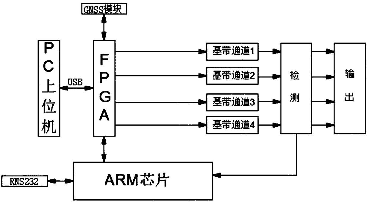
[0055] refer to figure 2 and 3 , this embodiment is further optimized on the basis of Embodiment 1, specifically, the device for generating an analog S-mode baseband signal further includes a GNSS module, and the GNSS module is connected to an FPGA wire.

[0056] The GPS and BD receiving components are reserved inside the GNSS module to complete the acquisition of parameters such as longitude, latitude, and altitude of the place where the device is used, which can be used as the actual coordinates of the ADS-B message encoding.

[0057] The commonly used ADS-B information data can be pre-input in the PC host computer without inputting the longitude, latitude and altitude parameters, and the GNSS module can be input to obtain the actual coordinates of the device used, so that the simulated S-mode baseband signal is more realistic.


PUM


Abstract

The invention discloses a method and device for simulating generation of an S-mode baseband signal, relates to the technical field of air traffic control monitoring, and aims to solve the problem thatan S-mode responder cannot effectively practically verify the S-mode signal during factory testing and outfield testing. The method comprises the steps that multiple pieces of simulated ADS-B messagedata are input in advance; an FPGA receives and analyzes the simulated ADS-B message data and then carries out baseband pulse information coding, and a simulated S-mode baseband signal is generated,wherein the FPGA controls baseband interchannel time delay during baseband coding; the simulated S-mode baseband signal and the running state of the device are detected. The device can simulate an avionic device to send out the S-mode baseband signal, and it is convenient for the S-mode responder to practically verify the S-mode signal during factory testing or outfield testing.

Description

technical field [0001] The invention relates to the technical field of air traffic control monitoring, in particular to a method and device for generating an analog S mode baseband signal. Background technique [0002] In the civil aviation system, the Mode S transponder is the main monitoring and communication equipment equipped by the aircraft. In most ground-to-air surveillance, Mode S signals are required to monitor aircraft. Because the S-mode signal is based on the aircraft electronic equipment, the S-mode transponder cannot effectively verify the S-mode signal in the factory test and field test. Therefore, a method and device that can simulate the generation of the S-mode baseband signal are needed. Contents of the invention [0003] In order to solve the problem that the S-mode transponder in the prior art cannot effectively verify the S-mode signal in the factory test and field test, a method and device for simulating the generation of the S-mode baseband signal ...

Claims


Application Information

Patent Timeline
Patent Type & Authority Applications(China)
IPC IPC(8): G01S7/40
CPCG01S7/40
Inventor 刘志勇林琳刘引川
Owner 四川省安道速博科技有限公司
Learn More