
Ultra-precise three-coordinate testing platform

A test platform and three-coordinate technology, applied in measuring devices, instruments, etc., can solve the problems of poor dynamic performance and large deformation of the measuring machine, and achieve the effects of reducing deformation, improving rigidity and simple installation.

Pending Publication Date: 2018-09-28
深圳市金园智能科技有限公司
View PDF0 Cites 6 Cited by
  • Summary
  • Abstract
  • Description
  • Claims
  • Application Information

AI Technical Summary

Problems solved by technology

In terms of structural design, according to different applicable objects and measurement accuracy requirements, the main structural forms of the existing three-dimensional precision measurement air flotation platforms are gantry type, bridge type, and cantilever type, and the mobile gantry type structure is used more. The vertical movement of measuring machines such as gantry coordinate measuring machines basically adopts the drive device placed on the cantilever beam of the gantry. For large-scale measuring machines, the increase in the stroke of the cantilever beam of the measuring machine will cause the span and height of the gantry to increase. Therefore, The quality of the gantry will increase a lot, and the deformation of the gantry will also increase accordingly due to its own weight, and the dynamic performance of the measuring machine will deteriorate. The axes must be on the same straight line, otherwise an error will occur. This error is called Abbe error. Usually, if the axis of the measuring instrument and the axis of the workpiece to be measured cannot be together, the distance must be shortened as much as possible to reduce the error. Value) and other defects have always been a big problem

Method used


Image

  • Ultra-precise three-coordinate testing platform
  • Ultra-precise three-coordinate testing platform
  • Ultra-precise three-coordinate testing platform

Examples


Embodiment

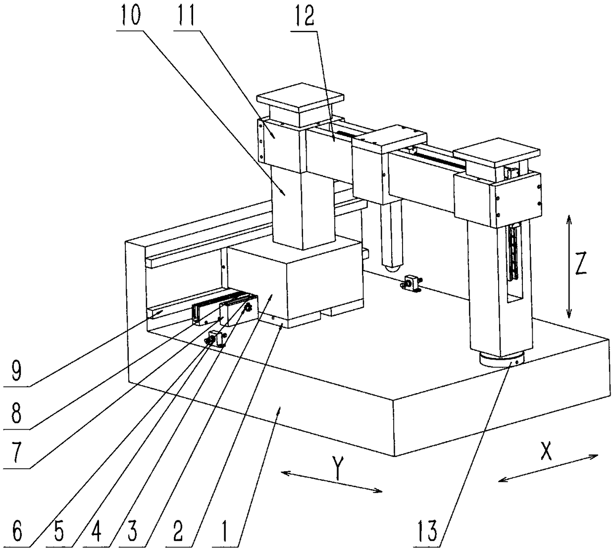
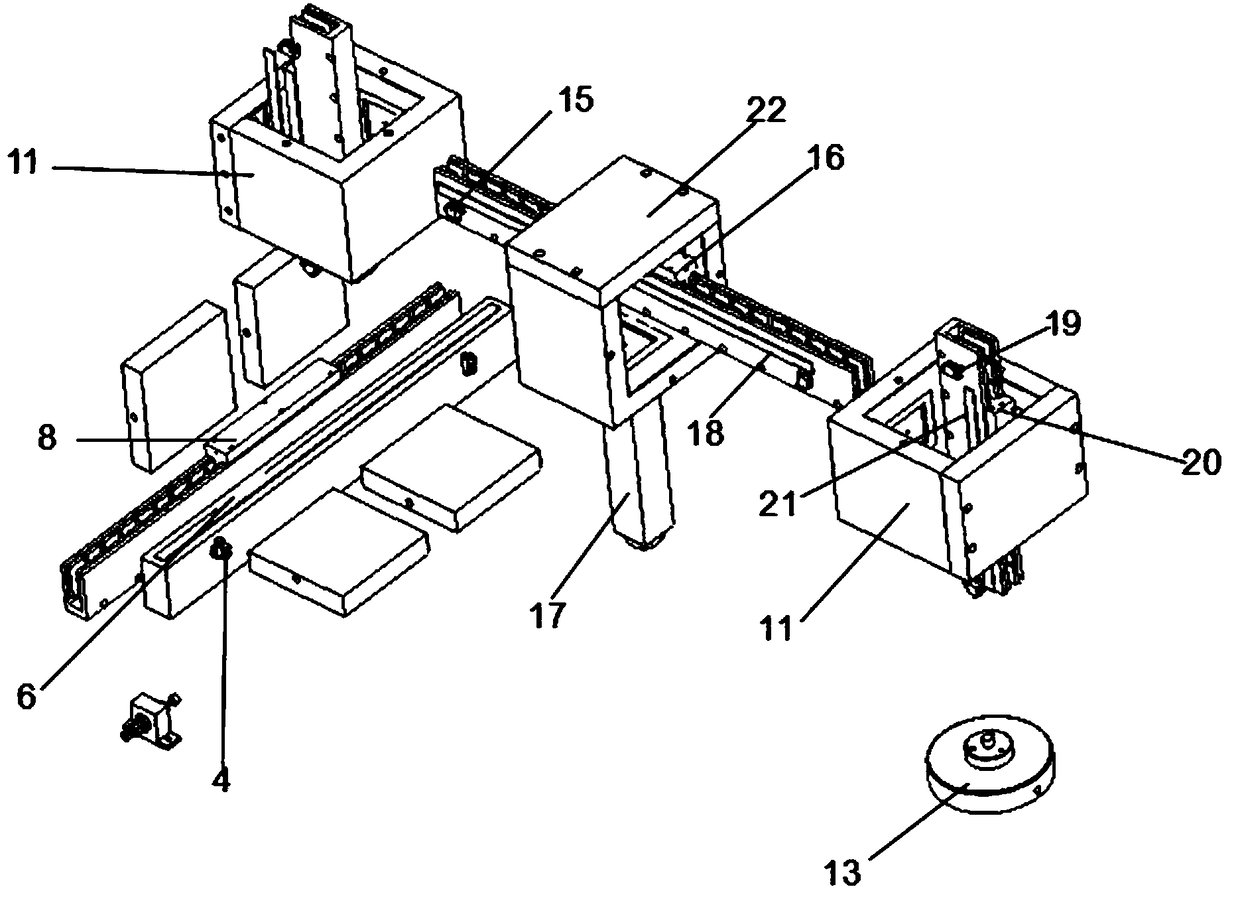
[0032] Embodiment: an ultra-precise three-coordinate test platform.

[0033] refer to Figure 1 to Figure 11 As shown, an ultra-precision three-coordinate test platform includes:

[0034] The base 1, the base 1 is spliced ​​into an "L" shape by a horizontally arranged smooth marble slab and a vertically arranged smooth marble slab, and the vertical end faces of the "L" shaped base 1 are parallel Two limit blocks 9 are arranged at intervals, a slideway is formed between the two limit blocks 9, and the surface of the marble base 1 is smooth and flat, which is conducive to the formation of a uniform air film on the surface of the vacuum preloaded air flotation component;

[0035] The support connector 3, which is arranged in a "7" shape, facilitates the support connector 3 to be in contact with the horizontal and vertical surfaces of the base 1 at the same time, and facilitates the installation of the bottom driving device and the measuring device ; The left edge and the bottom...


PUM


Abstract

The invention provides an ultra-precise three-coordinate testing platform, comprising a base, a support connector and a first Z-direction upright post and a second Z-direction upright post. A square flat-plate vacuum preloading air-flotation support is mounted on the support connector; the support connector is driven by an X-direction linear motor; the first Z-direction upright post is fixed on the top of the support connector, the second Z-direction upright post is mounted at one side, and a circular-plate vacuum preloading air-flotation support is mounted at the bottom of the second Z-direction upright post; a Z-direction linear motor is mounted on the Z-direction upright post and is connected with two first vacuum preloading air-flotation assemblies; a gantry cross beam is fixed betweentwo first vacuum preloading air-flotation assemblies, and a Y-direction linear motor is mounted on the gantry cross beam and connected with a second vacuum preloading air-flotation assembly. By the vacuum preloading air flotation technology, the testing platform can move rapidly without any friction on the X,Y and Z directions respectively, the moving on the Z direction is driven directly by thelinear motor and the two-way vacuum preloading air-flotation assemblies, and thus Abbe error on the Z-direction is reduced.

Description

technical field [0001] The invention relates to the technical field of testing equipment, in particular to an ultra-precise three-coordinate testing platform. Background technique [0002] The three-coordinate measuring machine plays an increasingly important role in modern manufacturing and national defense fields such as aviation and aerospace because of its high precision and strong flexibility. It can not only complete the measurement of geometric elements, curves and surfaces of various parts, but also can form an integrated system online with other processing equipment, such as machining centers, CNC machine tools, etc., to realize the integration of design, manufacturing and testing. With the advancement of science and technology and the country's emphasis on national defense technology and industry, the requirements for the measurement accuracy of three-coordinate measuring machines are also getting higher and higher. Improving measurement accuracy includes not only...

Claims


Application Information

Patent Timeline
IPC IPC(8): G01B21/00
CPCG01B21/00
Inventor 赵休金刘震
Owner 深圳市金园智能科技有限公司
Learn More