
Conveying vehicle for electromechanical equipment

A technology for electromechanical equipment and transport vehicles, which is applied to motor vehicles, trolleys, multi-axis trolleys, etc., can solve problems such as scratches on the bottom of electromechanical equipment, affect the appearance of electromechanical equipment, and reduce the service life of equipment, so as to improve the transmission distance and save energy. Effect of manpower and protection life

Inactive Publication Date: 2018-09-28
安徽目然信信息科技有限公司
View PDF0 Cites 3 Cited by
  • Summary
  • Abstract
  • Description
  • Claims
  • Application Information

AI Technical Summary

Problems solved by technology

[0002] With the improvement of living standards, people pay more and more attention to body shape. People often go to the exercise room to exercise. This requires the exercise room to introduce a large number of electromechanical equipment for fitness, and most of the electromechanical equipment is large in size and heavy in weight. When the electromechanical equipment is moved from the interior of the transport vehicle to the exit, a large amount of labor is required. When the labor input is unbalanced, the electromechanical equipment will tilt or even fall, resulting in damage to the electromechanical equipment. There are potential safety hazards. When the electromechanical equipment is dragged and moved, it will cause the bottom of the electromechanical equipment to rub against the plate of the transport vehicle, resulting in scratches on the bottom of the electromechanical equipment, seriously affecting the appearance of the electromechanical equipment, and even reducing the service life of the equipment, resulting in high investment costs , a serious waste of resources

Method used


Image

  • Conveying vehicle for electromechanical equipment
  • Conveying vehicle for electromechanical equipment

Examples


Embodiment Construction

[0018] The technical solutions in the embodiments of the present invention will be clearly and completely described below in conjunction with the accompanying drawings in the embodiments of the present invention. Obviously, the described embodiments are only a part of the embodiments of the present invention, rather than all the embodiments. Based on the embodiments of the present invention, all other embodiments obtained by a person of ordinary skill in the art fall within the protection scope of the present invention.

[0019] According to an embodiment of the present invention, a transport vehicle for electromechanical equipment is provided.

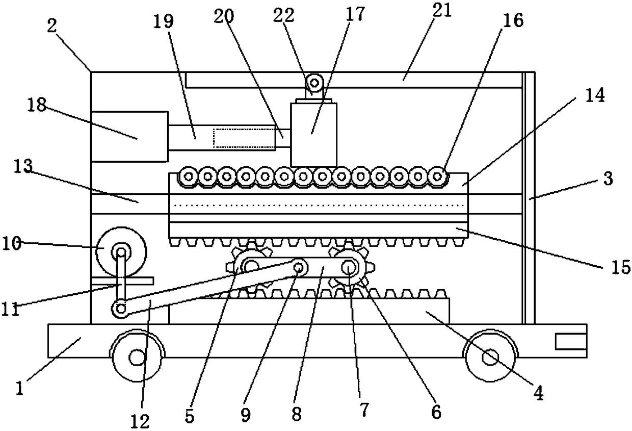
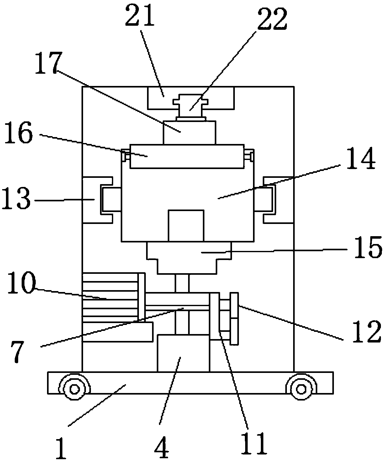
[0020] Such as Figure 1-2 As shown, the transport vehicle for electromechanical equipment according to the embodiment of the present invention includes a base 1, a box 2 is provided at the top of the base 1, and the box 2 is a cavity structure with lateral openings. One side is provided with a box door 3 adapted to the opening, the inner...


PUM


Abstract

The invention discloses a conveying vehicle for electromechanical equipment. The conveying vehicle comprises a base. A box is arranged at the top end of the base and is of a cavity structure with a lateral opening, and a box door matched with the opening is arranged on one side of the box; a first toothed plate is arranged at the bottom end of the inner side of the box, and a first rotating gear and a second rotating gear located on one side of the first rotating gear are arranged at the top end of the first toothed plate; rolling shafts are inserted in the middles of the first rotating gear and the second rotating gear in a penetrating mode, one end of each rolling shaft extends to the side wall of the box, and a connecting rod is arranged between the adjacent rolling shafts; the two endsof the connecting rod are both connected with the rolling shafts, and a rotating shaft is arranged in the middle of the connecting rod; and a rotating motor located on one side of the first rotatinggear is arranged in the box, and an output shaft of the rotating motor is connected with a rotating handle. The conveying device has the beneficial effects that convenience is brought for short-distance conveying of the electromechanical equipment, input of labor force is avoided, manpower is saved, the working efficiency is greatly improved, and capital input is reduced.

Description

Technical field [0001] The present invention relates to the technical field of electromechanical equipment, in particular to a transport vehicle for electromechanical equipment. Background technique [0002] With the improvement of living standards, people pay more and more attention to the body. People often go to the exercise room to exercise. This requires the exercise room to introduce a large number of electromechanical equipment for fitness. Most of the electromechanical equipment is larger and heavier. When the electromechanical equipment moves from the inside of the conveyor to the exit, a large amount of labor is required. When the labor input is unbalanced, the electromechanical equipment will tilt or even fall, resulting in damage to the electromechanical equipment, and there are potential safety hazards. When the electromechanical equipment is dragged and moved, it will cause friction between the bottom of the electromechanical equipment and the plate of the conveying...

Claims


Application Information

Patent Timeline
IPC IPC(8): B62B3/04B62B5/00
CPCB62B3/04B62B5/00B62B2203/74
Inventor 刘虎
Owner 安徽目然信信息科技有限公司
Learn More