
Vertical steel bar welding robot in construction site

A technology for welding robots and construction sites, applied in welding equipment, welding accessories, manufacturing tools, etc., can solve the problems of easy fatigue, severe sweating, hard quality and heavy weight

Active Publication Date: 2018-09-25
南通欧创自动化工程有限公司
View PDF5 Cites 2 Cited by
  • Summary
  • Abstract
  • Description
  • Claims
  • Application Information

AI Technical Summary

Problems solved by technology

The vertical welding that workers often encounter is all brand-new rebar, which is hard and heavy. The gloves and shoes used for labor protection equipment are quickly damaged. If the labor protection equipment is not replaced in time, the hands and feet may directly contact the steel bars, and it is easy to get an electric shock.
Coupled with humid and hot weather, the degree of sweating is severe, and the resistance of the human body is significantly reduced. Once an electric shock is made, it is not easy to get rid of it, and it is even more dangerous.
In addition, the general construction schedule of the construction industry is relatively tight. Generally, thousands of steel bars need to be welded on the first floor. The welding of the steel bars needs to be completed at one time. Labor and open-air work, the human body is extremely prone to fatigue, and the risk of electric shock is also greater

Method used


Image

  • Vertical steel bar welding robot in construction site
  • Vertical steel bar welding robot in construction site
  • Vertical steel bar welding robot in construction site

Examples


Embodiment Construction

[0016] Below in conjunction with accompanying drawing and specific embodiment the present invention is described in further detail:

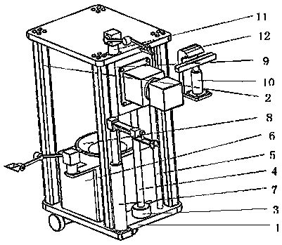
[0017] The invention provides a vertical steel bar welding robot on a construction site. The robot is a welding robot based on electroslag pressure welding, which can replace manual work, thereby reducing labor intensity, improving overall safety, and saving construction costs.

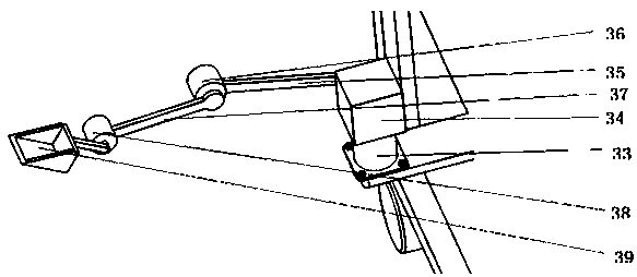
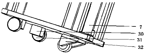
[0018] As an embodiment of the present invention, the present invention provides a vertical reinforcement welding robot on a construction site, including a support frame 1, a support rod 2, a screw motor 3, a transmission screw 4, a slide rod 5, a hydraulic oil tank 6, a hydraulic cylinder 7, Flux holding plate 8, vertical moving plate 9, auxiliary hydraulic cylinder 10, motor one 11, wide hook 12, hydraulic rod fork 13, main motor one 14, main motor two 15, motor two 16, rod one 17, motor three 18 , rod two 19, motor four 20, welding handle wire 21, vertical hydraulic ...


PUM


Abstract

The invention relates to a vertical steel bar welding robot in a construction site. A hydraulic oil tank is arranged on a bottom plate of a support frame, and a flux containing plate is arranged on the hydraulic oil tank; a screw motor is embedded in one side of the bottom plate of the support frame and fixedly connected with one end of a transmission screw; a hydraulic cylinder is arranged on thebottom plate of the support frame; a vertical moving plate is in threaded connection with the transmission screw; a main motor I is fixed on the vertical moving plate, a shell of a main motor II is fixedly connected with the main motor I, the root of a wide hook is fixedly connected with the main motor II, and an auxiliary hydraulic cylinder is fixed on the wide hook; a welding wire is fixed on atop plate of the support frame through a mechanical arm I; the hydraulic cylinder is matched with a vertical hydraulic rod by a moving pair, the vertical hydraulic rod controls work of a pair of semi-circular drums through a mechanical arm II, a digging tool is installed on an extension plate at one corner of the hydraulic oil tank through a mechanical arm III, and a wheel driving mechanism is arranged at the bottom of the bottom plate of the support frame. The welding robot is based on electroslag pressure welding and can replace manual operation, thereby reducing labor intensity, improvingoverall safety and saving construction cost.

Description

technical field [0001] The invention relates to the field of construction welding robots, in particular to a construction site vertical reinforcement welding robot. Background technique [0002] The electroslag pressure welding commonly used in construction sites is a fusion welding method that uses the resistance heat generated by the current passing through the liquid slag for welding. The secondary no-load voltage of the electroslag pressure welding machine is generally around 65V-80V, its working time is about 20%, and the no-load time is about 80%. The steel bars are all connected to the metal of the entire building. The welded steel bars are densely packed, the work site is narrow, and the steel bars are piled up on the ground. The operators work for a long time. Once they touch the power supply of the welding handle, there is a risk of electric shock. The vertical welding that workers often encounter is all brand-new rebar, which is hard and heavy. The gloves and sho...

Claims


Application Information

Patent Timeline
Patent Type & Authority Applications(China)
IPC IPC(8): B23K9/00B23K9/12B23K9/32
CPCB23K9/0026B23K9/12B23K9/32B23K9/324
Inventor 孙雪王艳孙萍
Owner 南通欧创自动化工程有限公司
Learn More