
Control circuit, power amplifier circuit and control method

A power amplification circuit and control circuit technology, applied in the direction of amplifiers, amplifiers with semiconductor devices/discharge tubes, radio frequency amplifiers, etc., can solve the problems of reducing the maximum output power of GSM radio frequency power amplifiers, reducing the efficiency of GSM radio frequency power amplifiers, etc. , to achieve the effect of reducing chip area and cost

Active Publication Date: 2018-09-21
SHANGRUI MICROELECTRONICS SHANGHAI
View PDF5 Cites 4 Cited by
  • Summary
  • Abstract
  • Description
  • Claims
  • Application Information

AI Technical Summary

Problems solved by technology

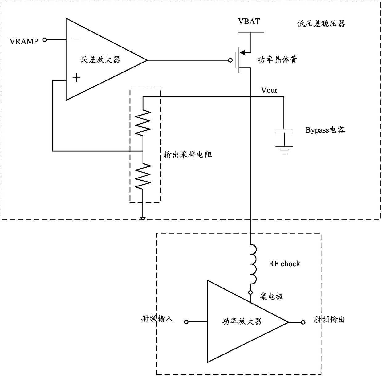
[0003] However, at present, the output power of the GSM RF power amplifier is controlled through the LDO. Because the power transistor of the LDO will produce a voltage drop, the collector voltage Vout of the GSM RF power amplifier is always lower than the power supply voltage VBAT, thereby reducing the GSM RF power. The maximum output power of the amplifier reduces the efficiency of the GSM RF power amplifier

Method used


Image

  • Control circuit, power amplifier circuit and control method
  • Control circuit, power amplifier circuit and control method
  • Control circuit, power amplifier circuit and control method

Examples


Embodiment Construction

[0036] Usually, power amplifiers include GSM radio frequency power amplifiers, etc., figure 1 It is a schematic diagram of the power control circuit of the GSM radio frequency power amplifier, figure 1 The power control process of the power control circuit shown specifically includes: when the reference control voltage VRAMP increases, the source terminal voltage Vout of the power transistor increases, which in turn causes the collector voltage of the GSM radio frequency power amplifier to increase, causing the GSM radio frequency power amplifier to increase. The output power increases according to the square relationship with the drain terminal voltage Vout; when the reference control voltage VRAMP decreases, the source terminal voltage Vout of the power transistor decreases, which in turn causes the collector voltage of the GSM RF power amplifier to decrease, resulting in a GSM RF power The output power of the amplifier decreases as the square of the drain voltage Vout. Amo...


PUM


Abstract

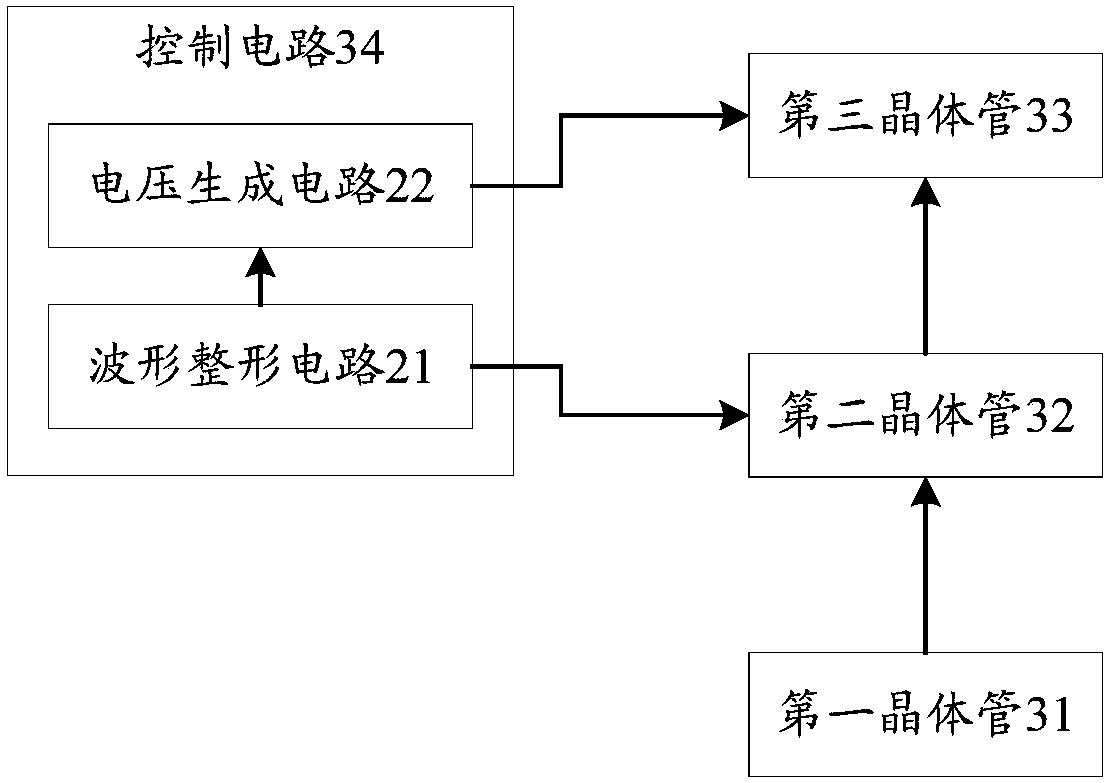
The invention discloses a control circuit applied to a power amplifier circuit. The power amplifier circuit comprises a first transistor, a second transistor and a third transistor, wherein the thirdtransistor is directly connected to a power supply through an inductor; the control circuit comprises a waveform shaping circuit and a voltage generation circuit, wherein the waveform shaping circuitis used for generating a first current through a reference voltage control signal of the power amplifier circuit, comparing the first current with a reference current value to obtain a second current,generating a mirror current by utilizing the second current, and obtaining a first grid voltage by utilizing the mirror current, wherein the first grid voltage is used for the second transistor to control the first transistor to amplify an input signal in order to obtain an output signal; and the voltage generation circuit is used for generating a second grid voltage by utilizing the first grid voltage, and controlling the third transistor to output the output signal meeting the stable output characteristic by utilizing the second grid voltage. The invention further discloses the power amplifier circuit and a control method.

Description

technical field [0001] The invention relates to a power amplifying circuit, in particular to a control circuit, a power amplifying circuit and a control method. Background technique [0002] At present, as the Silicon On Insulator (SOI, Silicon On Insulator) process becomes more and more mature, implementing a radio frequency power amplifier (PA, Power Amplifier) ​​using the SOI process has more and more cost advantages. Global System for Mobile Communication (GSM, Global System for Mobile Communication) power amplifier is a kind of radio frequency power amplifier. In the power control circuit of the existing commonly used GSM radio frequency power amplifier, usually, the reference control voltage VRAMP passes through the low dropout regulator (LDO, Low DropOut regulator) controls the collector voltage of the GSM RF power amplifier, and then realizes the control of the output power of the GSM RF power amplifier. The LDO includes an error amplifier and a power transistor. ...

Claims


Application Information

Patent Timeline
IPC IPC(8): H03F1/02H03F3/195H03F3/213
CPCH03F1/0211H03F3/195H03F3/213H03F2200/451
Inventor 李咏乐苏强奕江涛
Owner SHANGRUI MICROELECTRONICS SHANGHAI
Learn More