Linear vibrating motor

A linear vibration and motor technology, applied in the direction of electrical components, electromechanical devices, etc., can solve the problems of low stability and reliability of linear vibration motors, restrict the improvement of linear vibration motor performance, and inconvenient disassembly and maintenance of linear vibration motors. Convenience of installation, solving the cumbersome installation method, and the effect of convenient installation

Pending Publication Date: 2018-09-21
苏州国华特种线材有限公司
View PDF0 Cites 1 Cited by
  • Summary
  • Abstract
  • Description
  • Claims
  • Application Information

AI Technical Summary

Problems solved by technology

[0003] Most of the existing elastic supports of linear vibration motors are made of simple metal materials. It is difficult for elastic supports made of metal materials to achieve a good unity with the performance of linear vibration motors in terms of rigidity and compliance, resulting in linear vibration motors The stability and reliability of the linear vibration motor are low, which seriously restricts the improvement of the performance of the linear vibration motor. At the same time, the installation method of the linear vibration motor is relatively cumbersome, and it is inconvenient to disassemble and maintain the linear vibration motor. Now a linear vibration motor is urgently needed to solve the above problems.

Method used


Image

  • Linear vibrating motor
  • Linear vibrating motor
  • Linear vibrating motor

Examples


Embodiment Construction

[0021] In order to make the technical means, creative features, goals and effects achieved by the present invention easy to understand, the present invention will be further described below in conjunction with specific embodiments.

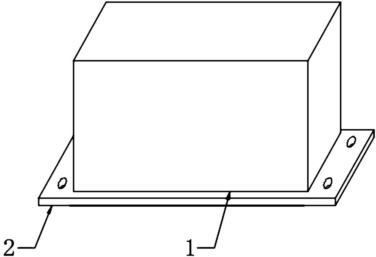
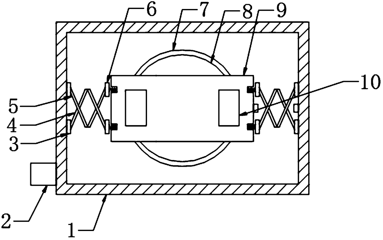
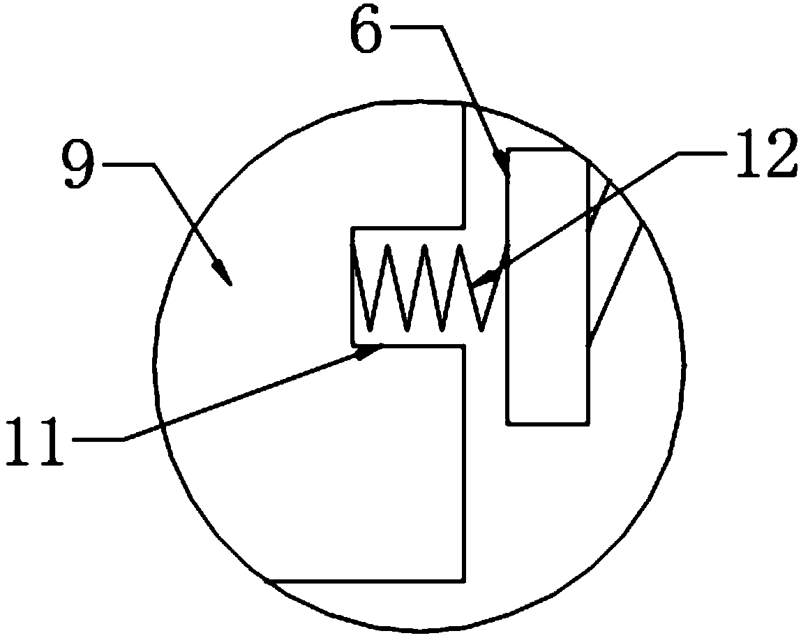
[0022] see Figure 1-Figure 5 , the present invention provides a technical solution: a linear vibration motor, including a housing 1, a vibrating block 9, a coil 7, and a mounting plate 13. Threaded holes 15 are provided on the left and right sides of the upper end surface of the mounting plate 13, and the upper end surface of the mounting plate 13 is provided with Raised side 14, housing 1 is installed on the upper side of raised side 14, power connection plate 2 is installed on the lower side of the left end surface of housing 1, winding post 8 is installed on the inner lower side of housing 1, and coil is provided on the ring side of winding post 8 7. Connectors 1 are provided on the left and right sides of the inner wall of the shell 1. A vibr...


PUM


Abstract

The invention provides a linear vibrating motor. The linear vibrating motor comprises connecting components I, elastic components I, elastic components II, connecting components II, grooves, springs,a mounting plate, a protruded edge and two threaded holes, wherein the two threaded holes are formed in the left and right sides of the upper end surface of the mounting plate, and the protruded edgeis arranged on the upper end surface of the mounting plate. According to the design, the problem of the mounting manner of an original linear vibrating motor is tedious is solved; the connecting components I are arranged on the left and right sides of the inner wall of the shell, the grooves are formed in the left and right end surfaces of a vibration block, the springs are mounted in the grooves,the connecting components II are mounted outside the springs, the elastic components I are mounted between the connecting components II and the connecting components I, and the elastic components IIare mounted to be crossed with the elastic components I; the problem that the original vibration motor has defects on the vibration performance is solved; and the linear vibrating motor is reasonablein structure, good in vibration performance, convenient to mount and high in working efficiency.

Description

technical field [0001] The invention relates to a linear vibration motor, which belongs to the technical field of linear vibration motors. Background technique [0002] With the development of communication technology, portable electronic products, such as mobile phones, handheld game consoles, or handheld multimedia entertainment devices, have entered people's lives. In these portable electronic products, micro vibration motors are generally used for system feedback. For example, the incoming call notification of the mobile phone, the vibration feedback of the game console, etc. [0003] Most of the existing elastic supports of linear vibration motors are made of simple metal materials. It is difficult for elastic supports made of metal materials to achieve a good unity with the performance of linear vibration motors in terms of rigidity and compliance, resulting in linear vibration motors The stability and reliability of the linear vibration motor are low, which seriousl...

Claims


Application Information

Patent Timeline
IPC IPC(8): H02K33/04
CPCH02K33/04
Inventor 王云喜
Owner 苏州国华特种线材有限公司
Why Eureka
Try Eureka