
Direct current breaker for disconnecting fault current, control system and control method

A DC circuit breaker and fault current technology, which is applied in the direction of circuit devices, emergency protection circuit devices, emergency protection devices for automatic disconnection, etc., can solve the problem of insufficient recovery of the dielectric strength of the mechanical fracture medium and the extremely high withstand voltage requirements of the main circuit charging power supply. High, unreliable breaking and other problems, to achieve the effect of no need for heat dissipation measures, improve breaking reliability, and high breaking reliability

Pending Publication Date: 2018-09-21
XI AN JIAOTONG UNIV
View PDF0 Cites 9 Cited by
  • Summary
  • Abstract
  • Description
  • Claims
  • Application Information

AI Technical Summary

Problems solved by technology

[0003] After the traditional DC circuit breaker is broken, the mechanical switch needs to withstand the shutdown voltage. Due to the insufficient recovery of the dielectric strength of the mechanical fracture medium, heavy breakdown is prone to occur and cause breaking failure.
[0004] The capacitor charging circuit in the traditional transfer current circuit is directly connected to the main circuit without isolation, the charging power supply and the main circuit will interfere during the disconnection process, and the withstand voltage requirements for the main circuit charging power supply are very high, and the disconnection is unreliable

Method used


Image

  • Direct current breaker for disconnecting fault current, control system and control method
  • Direct current breaker for disconnecting fault current, control system and control method
  • Direct current breaker for disconnecting fault current, control system and control method

Examples


Embodiment Construction

[0022] Attached below Figure 1-21 and Examples describe the present invention in detail, but not as a limitation of the present invention.

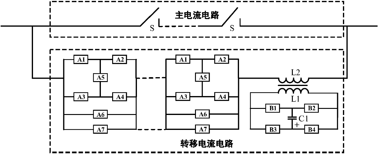
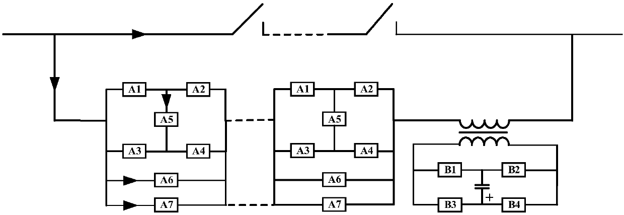
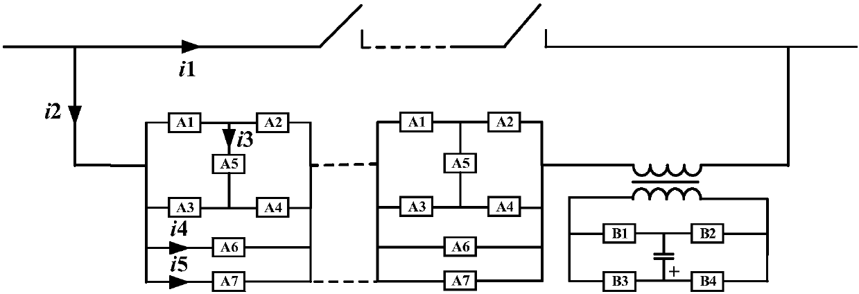
[0023] Such as figure 1 As shown, the present invention provides a DC circuit breaker for breaking fault currents, including a main current circuit and a transfer current circuit. In order to better illustrate the breaking process of the circuit breaker, this embodiment provides a structural schematic diagram of the current flow of the DC circuit breaker from left to right, as shown in figure 2 shown.

[0024] Such as figure 1 , figure 2 As shown, the DC circuit breaker includes a main current circuit and a transfer current circuit, and the main current circuit and the transfer current circuit are connected in parallel.

[0025] The main current circuit consists of one or more high-speed mechanical switches connected in series. In order to prevent breakdown after the current transfer of the high-speed mechanical switch, the main ...


PUM


Abstract

The invention discloses a direct current breaker for disconnecting a fault current. The direct current breaker comprises a main current circuit and a transfer current circuit which are connected in parallel, wherein the main current circuit comprises one or more tandem high-speed mechanical switches; and the transfer current circuit comprises a magnetic coupling transfer module and a solid-state switch circuit which are connected in series. The invention further discloses a control system and method for disconnecting the fault current. According to the direct current breaker, the system and the method, the rapid disconnection of the current can be realized, the volume of the current breaker is effectively reduced, and the manufacturing cost of the current breaker is effectively lowered; and by virtue of the magnetic coupling transfer module, the rapid transfer of the current is realized, the isolation between a secondary charging circuit and a main loop is realized, the transfer speedis high, and the disconnection reliability is high; and meanwhile, a follow current circuit is connected with the high-speed mechanical switches in parallel, so that the disconnection failure caused due to the restriking of a connection hole after the breakage of the current breaker is avoided, and the disconnection reliability is further improved.

Description

technical field [0001] The invention belongs to the technical field of electrical equipment, and in particular relates to a DC circuit breaker, a control system and a method for breaking fault currents. Background technique [0002] The hybrid circuit breaker composed of high-speed mechanical switches and power semiconductor devices has the advantages of large current capacity, fast shutdown speed, and strong current limiting capability, and has become a research hotspot in the field of large-capacity system breaking. Compared with other hybrid solutions, the hybrid DC circuit breaker scheme using power semiconductor devices with full control function to break current has the advantages of faster breaking speed and more favorable breaking rated current. However, when using a fully-controlled power semiconductor device to break current, it is usually necessary to connect the fully-controlled power semiconductor device in series with a mechanical switch to realize current tran...

Claims


Application Information

Patent Timeline
Patent Type & Authority Applications(China)
IPC IPC(8): H02H7/26H02H3/087
CPCH02H3/087H02H7/268
Inventor 杨飞吴翊吴益飞荣命哲纽春萍易强胡杨
Owner XI AN JIAOTONG UNIV
Learn More