
Sampling device for extracting smoke from high-temperature flue gas

A sampling device, high-temperature flue gas technology, applied in the field of mechanical equipment, can solve the problems of inconvenient soot or soot analysis, unfavorable to maintain the original phase of soot or soot, loss of value, etc., so as to maintain the original phase composition and facilitate detection. Analytical research, the effect of preventing chemical reactions

Pending Publication Date: 2018-09-21
CENT SOUTH UNIV
View PDF2 Cites 4 Cited by
  • Summary
  • Abstract
  • Description
  • Claims
  • Application Information

AI Technical Summary

Problems solved by technology

This kind of device is suitable for flue gas sampling, but when it is used for soot or soot sampling, due to the low cooling efficiency, the soot or soot cannot be cooled rapidly, which may cause the soot or soot sample to react in a molten state, which is not conducive to Keep the original phase of soot or soot, which will lead to the distortion of subsequent detection and analysis results and lose its value, and the amount of soot or soot extracted by it is small, which is not convenient for the analysis of soot or soot
[0004] In addition, there are sampling devices with other structures, which are either complicated in structure, high in cost and inconvenient to use, or unsuitable for sampling dusty flue gas in high temperature metallurgical furnaces

Method used


Image

  • Sampling device for extracting smoke from high-temperature flue gas
  • Sampling device for extracting smoke from high-temperature flue gas
  • Sampling device for extracting smoke from high-temperature flue gas

Examples


Embodiment 1

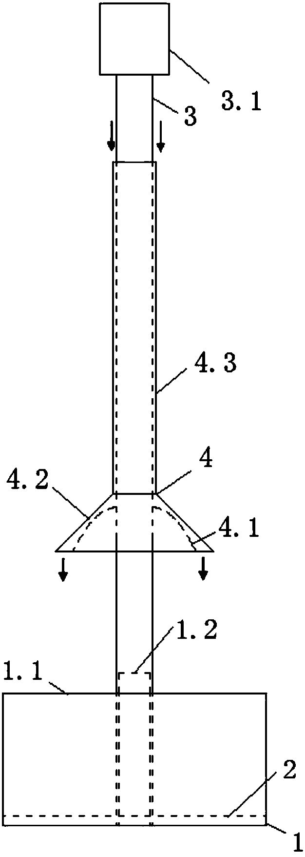
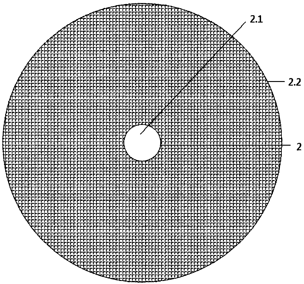
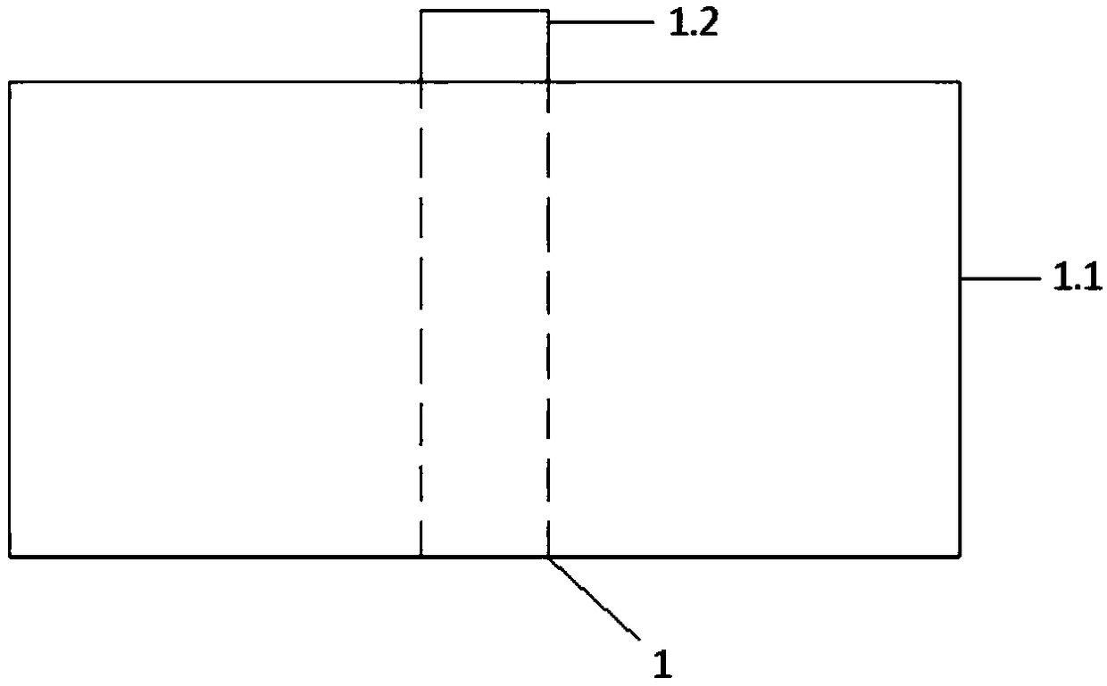
[0031] see Figure 1-Figure 3 ( figure 1 The direction of the middle arrow is the direction of water flow), a sampling device for extracting dust from high-temperature flue gas, including a collecting part 1, a filtering part 2, a supporting part 3 and a water curtain assembly 4, and the specific structure is as follows:

[0032] The upper end of the support member 3 is used for holding by hand-held or electric equipment, and its lower end is detachably connected to the collection member 1. Preferably, the support member 3 is a support round bar, and the upper end of the support round bar is provided with a A circular or square handle 3.1 held by a hand-held or electric device, the lower end of the supporting round rod is a hollow structure with a first external thread and a first internal thread.

[0033] The collection part 1 is used to collect the mixed liquid of water and smoke obtained through the water curtain assembly 4, preferably: the collection part 1 includes a col...


PUM

PropertyMeasurementUnit
thicknessaaaaaaaaaa

Abstract

The present invention provides a sampling device for extracting smoke from high-temperature flue gas. The device comprises a collecting assembly, a filtering assembly, a supporting assembly and a water curtain assembly. By applying the technical scheme, the effect that the overall structure is precise and simplified is achieved; water flow is guided by a flow limiting curved surface and a flow guiding surface in the water curtain assembly, and the minimum cross-sectional position between the flow limiting curved surface and the flow guiding surface is changed along with water flow speed conditions; when the water flow flows through a gap between the flow limiting curved surface and the flow guiding surface, it can be ensured that the water flow at an outlet stays in a flowing downward state, and a uniform water curtain is formed along the circumference; when the flue gas passes through the water curtain, the smoke carried in the flue gas is captured by the water curtain, and collectionof the smoke is facilitated; the smoke carried in the high-temperature flue gas is captured by the water curtain, then falls into the collecting assembly along with the water curtain and is quenchedby water so that a further chemical reaction of the smoke can be prevented, and therefore original material phase compositions of the smoke is maintained. Through design of the filtering assembly, thewater and a smoke sample can be effectively separated, and convenience is provided extraction of the smoke sample.

Description

technical field [0001] The invention relates to the technical field of mechanical equipment, in particular to a sampling device for extracting smoke from high-temperature smoke. Background technique [0002] In order to study the reaction status and reaction mechanism in the pyrometallurgical furnace, it is necessary to extract the soot sample from the pyrometallurgical furnace, and then detect and analyze the particle size and composition of the soot sample; Oxidation occurs when exposed to air, and rapid cooling of the soot is also required to ensure the original characteristics of the chemical composition of the dust sample. However, the materials entering the furnace react violently in the high-temperature metallurgical furnace, making the temperature in the furnace reach above 1250°C, and most of the high-temperature metallurgical furnaces have high flue gas flow rates, low density of smoke and dust, and are easy to bond, which brings great pressure to the extraction of...

Claims


Application Information

Patent Timeline
Patent Type & Authority Applications(China)
IPC IPC(8): G01N1/22G01N1/34
CPCG01N1/22G01N1/2205G01N1/2226G01N1/34G01N2001/2282G01N2001/2235
Inventor 陈卓吴辉祝振宇宋彦坡
Owner CENT SOUTH UNIV
Learn More