
An integrated pipe body cutting and stacking mechanism for automobiles

A cutting mechanism and integrated technology, applied in the field of auto parts processing, can solve the problems of low cutting efficiency, inconvenient cleaning, no separation, etc., to improve the efficiency of pipe delivery, cutting efficiency, and the continuity of feeding Effect

Inactive Publication Date: 2019-08-13
CHINA UNIV OF PETROLEUM (EAST CHINA)
View PDF8 Cites 0 Cited by
  • Summary
  • Abstract
  • Description
  • Claims
  • Application Information

AI Technical Summary

Problems solved by technology

This type of cutting method has the following disadvantages: First, the straight pipes to be cut are mostly put on the shelves manually, that is, the single straight pipes to be cut are placed on the workbench in sequence, and after being clamped by the clamping mechanism, the straight pipes are driven to feed To the cutting knife, a single straight pipe to be cut needs to be cut several times to complete the cutting process, resulting in low cutting efficiency; secondly, when the cutting knife cuts the straight pipe, the cut straight pipe is under the high-speed rotation force of the cutting knife Under the action of the cutting tool, it will fly out of the workbench, which is not only inconvenient for subsequent stacking, but also poses certain safety hazards; third, the straight pipes cut by the cutting knife include several straight pipes that meet the specification length and a section that does not meet the specification length. The leftover material, the straight pipe and the leftover material of the prior art are all dropped to the same place, without separation, which brings new work requirements for the subsequent separation; four, the prior art pipe cutting machine lacks the stacking machine used in conjunction with it mechanism, the straight pipe after cutting is mostly stacked by personnel, which is not conducive to the continuity and efficiency of equipment processing
The cooling device for cutting in the prior art, such as an aluminum rod cutting machine with a cooling mechanism disclosed in patent application 201320714314.9, mostly cools the surface of the cutting knife by continuously injecting cooling liquid into the outer surface of the cutting knife; this type of technical solution has the following deficiencies : One, the cooling is mostly concentrated on the outer surface of the cutting knife, the internal heat transfer effect of the cutting knife needs to be improved, and there is a deficiency of low cooling uniformity; second, a large amount of cooling liquid is directly discharged from the bottom of the cutting knife, which is easy on the one hand It corrodes the machine tool and is inconvenient to clean; on the other hand, it will also lead to waste of coolant

Method used


Image

  • An integrated pipe body cutting and stacking mechanism for automobiles
  • An integrated pipe body cutting and stacking mechanism for automobiles
  • An integrated pipe body cutting and stacking mechanism for automobiles

Examples


Embodiment 1

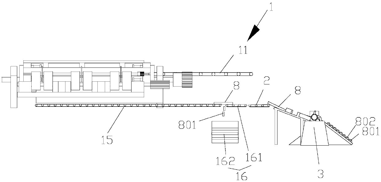
[0054] Such as figure 1 As shown, the present invention discloses an integrated pipe body cutting and stacking mechanism for automobiles, including a cutting mechanism 1 , a transfer mechanism 2 and a stacking mechanism 3 . The cutting mechanism 1 is used to cut the straight pipe 7 to be cut, and the transfer mechanism 2 is used to transport the cut straight pipes 8 to the stacking mechanism 3 for stacking.

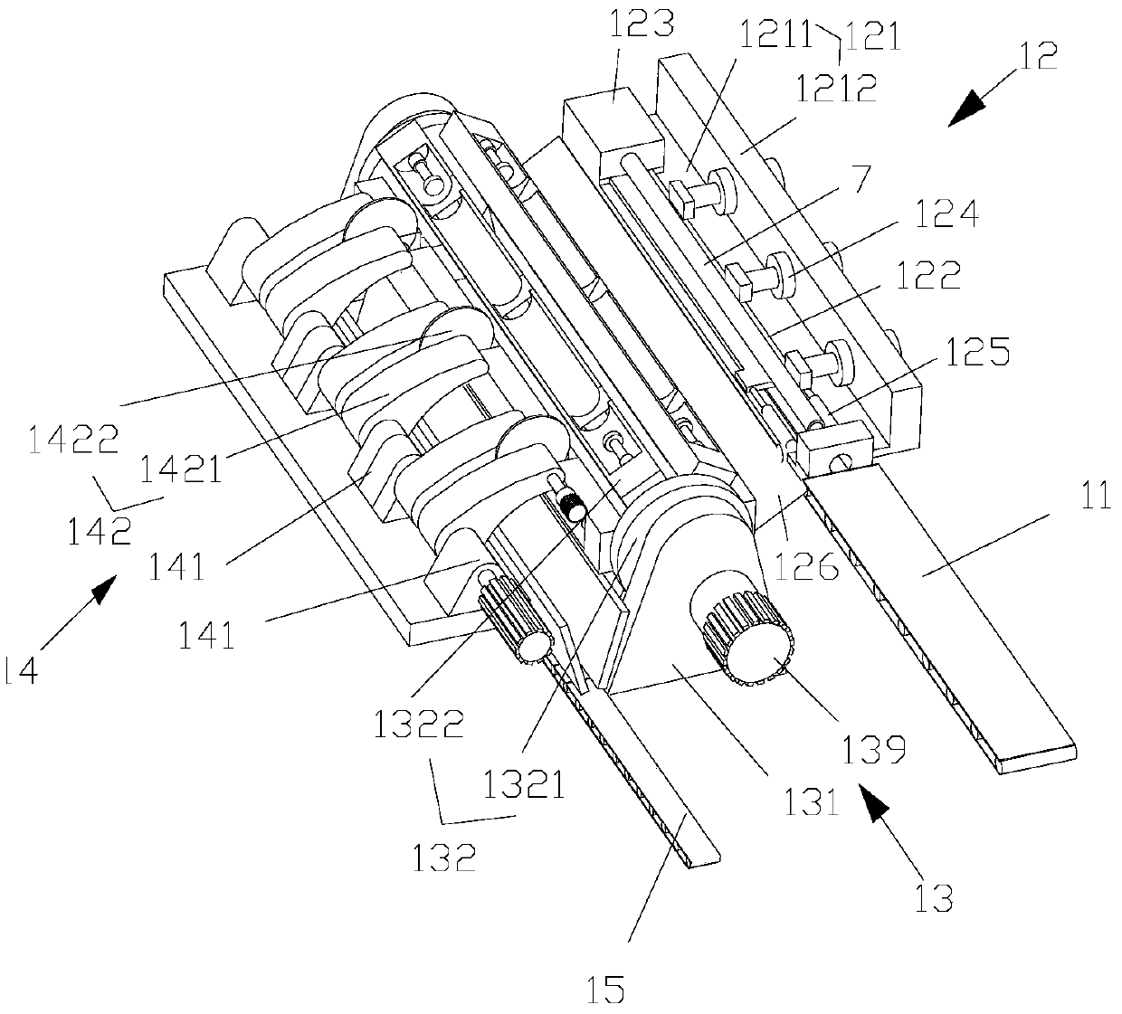
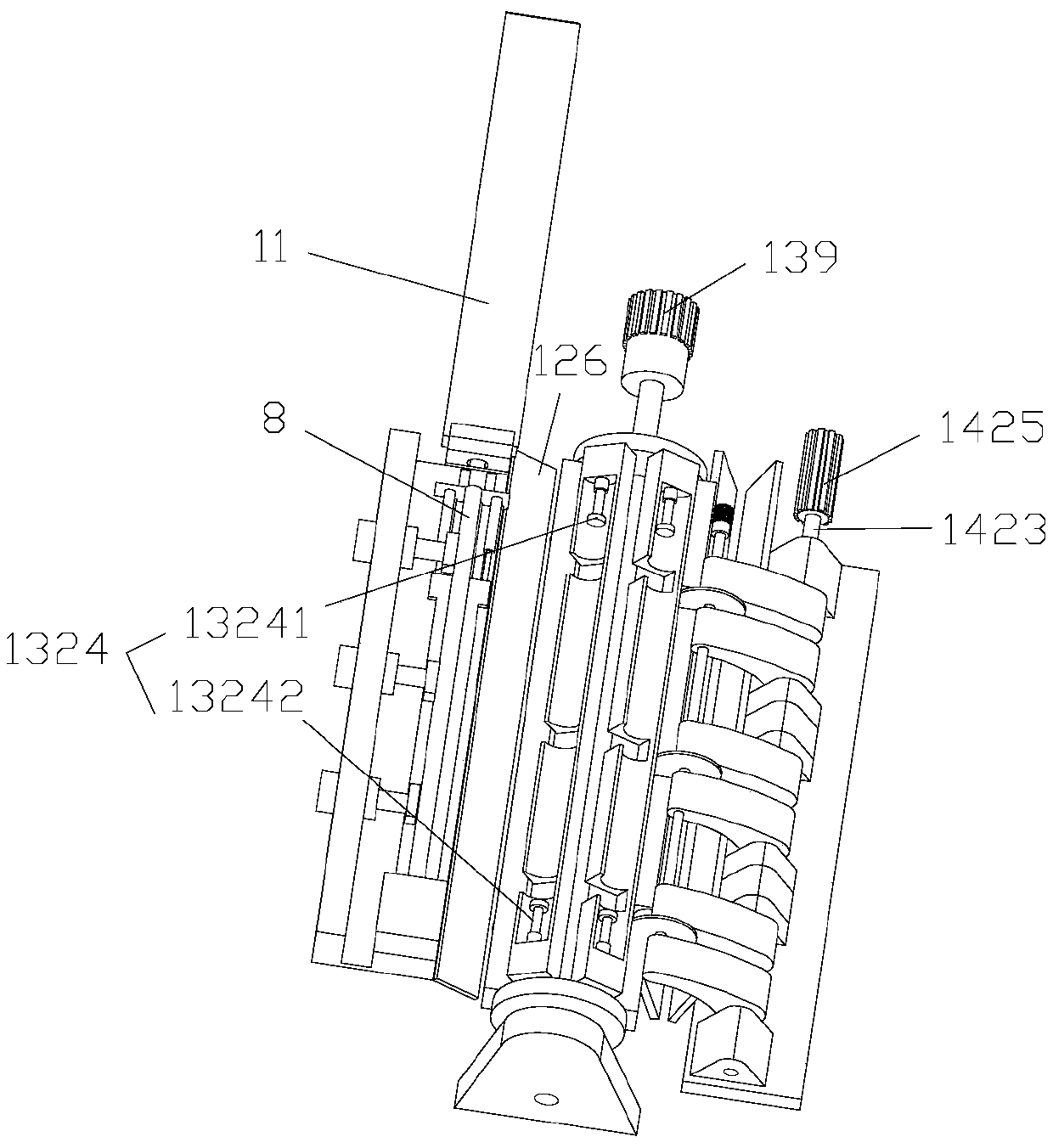
[0055] Such as figure 1 , 2 As shown, the cutting mechanism 1 includes a first conveying device 11 , an alignment and unloading device 12 , a rotary feeding device 13 , a cutting machine 14 , a second conveying device 15 , and a leftover material separating device 16 . The first conveying device 11 is used to transport the straight pipe 7 to be cut into the alignment and unloading device 12, and the alignment and unloading device 12 is used to align the straight pipe 7 to be cut and delivered thereinto and align the aligned straight pipe 8 is unloaded into the rotary f...

Embodiment 2

[0065] Such as Figure 2-4 As shown, the difference of this embodiment compared with the above embodiments is that this embodiment provides a cutting machine 14, including a knife seat 141, a swing cutting device, and a plurality of swing cutting devices corresponding to the same feeding The cutouts 13222 on the block 1322 are in one-to-one correspondence. Each oscillating cutting device includes a cantilever 1421 and a cutting knife 1422. The lower end of the cantilever 1421 is rotatably connected to the knife seat 141 by a cutter shaft 1423, and the higher end of the cantilever 1421 is connected to the cutting knife by a knife shaft 1424. 1422 is rotationally connected, the cutter shaft 1423 is driven to rotate by the cutting motor 1425, and the cutter shaft 1424 is driven to rotate by the cutter motor 1426, preferably, between the cutter shaft 1424 and the cantilever 1421, between the knife seat 141 and the cutter shaft 1423 Bearings are set between them. The cutting knif...

Embodiment 3

[0069] The difference between this embodiment and the above embodiment is that: the cutting machine 14 further includes a cooling system, and the cooling system is used to cool the cutting blade 1422 . The cooling system includes a liquid inlet pipe (not shown in the figure), a liquid outlet pipe (not shown in the figure), and the cutter shaft 1424 is a hollow structure, such as Figure 12-14 As shown, a liquid injection channel 14221 is provided inside the cutting knife 1422 , and the liquid injection channel 14221 communicates with the inner cavity of the knife shaft 1424 . Several liquid injection channels 14221 diverge from the center of the cutting knife 1422 to the edge of the cutting knife 1422 in a radial shape. One end of the cutter shaft 1424 is provided with a liquid inlet (not shown in the figure), and the other end of the cutter shaft 1424 is provided with a liquid outlet (not shown in the figure), and a water outlet is provided at the liquid outlet and the liquid...


PUM


Abstract

The invention discloses an integral pipe body cutting and stacking mechanism for a car. The integral pipe body cutting and stacking mechanism comprises a cutting mechanism, a transferring mechanism and a stacking mechanism. The cutting mechanism is used for cutting straight pipes to be cut. The transferring mechanism is used for conveying the cut straight pipes to the stacking mechanism to be stacked. The cutting mechanism comprises a first conveying device, a straight pipe aligning and blanking device, a rotary feeding device, a cutting machine, a second conveying device and a leftover material separating device. The invention further discloses a method for using the integral pipe body cutting and stacking mechanism for the car to cut and stack pipe bodies for the car. The integral pipe body cutting and stacking mechanism has the beneficial effects that the cutting efficiency is improved, the cutting precision is high, cut leftover materials can be separated conveniently, and the straight pipes can be stacked conveniently.

Description

technical field [0001] The invention relates to the technical field of auto parts processing, in particular to an integrated pipe body cutting and stacking mechanism for automobiles. Background technique [0002] After casting and heat treatment, the blank tubes for automobile processing need to be cut into tubes of equal length for processing in the next process. [0003] Most of the pipe cutting machines in the prior art are linear pipe cutting machines, such as a pipe cutting machine disclosed in patent application 201510966136.2 or a pipe cutting machine disclosed in patent application 201620667104.2. The holding mechanism clamps the main straight pipe to be cut, and then cuts the straight pipe by swinging the cutting knife. This type of cutting method has the following disadvantages: First, the straight pipes to be cut are mostly put on the shelves manually, that is, the single straight pipes to be cut are placed on the workbench in sequence, and after being clamped by...

Claims


Application Information

Patent Timeline
Patent Type & Authority Patents(China)
IPC IPC(8): B23D21/00B23D33/02
CPCB23D21/00B23D33/02
Inventor 王龙庭徐兴平汪海王斌王言哲祖国强冯帆刘广斗常汉卿
Owner CHINA UNIV OF PETROLEUM (EAST CHINA)
Learn More