
Clamping mechanism suitable for pipeline transportation

A technology of clamping mechanism and pipes, which is applied in the direction of transportation and packaging, to prevent mechanical damage, containers, etc. It can solve the problems of low efficiency of pipe delivery, poor stability, and the inability to fix both ends of the pipe at the same time, so as to achieve the goal of pipe delivery High efficiency and improved stability

Inactive Publication Date: 2018-11-09
孙伟鹏
View PDF0 Cites 0 Cited by
  • Summary
  • Abstract
  • Description
  • Claims
  • Application Information

AI Technical Summary

Problems solved by technology

[0004] The main purpose of the present invention is to overcome the deficiencies of the prior art and provide a clamping mechanism suitable for pipeline transportation to solve the problem that the pipeline cannot be fed into the pipeline at the same time in opposite directions, the efficiency of the pipeline is low, the stability of the pipeline is poor during transportation, and it is impossible to pass through the pipeline. The conveying movement pushes up the pneumatic inner rod and locks the two fixed shaft disks to realize the fixation of the pneumatic inner rod, which further improves the stability of pipeline transportation; The pressure shaft ring locks the two contact pressure rings through the locking tooth plate to realize the fixation of the two spring devices and the two contact pressure rings; after the transportation is completed, the two ends of the pipeline cannot be fixed and the middle part can be fixed at the same time

Method used


Image

  • Clamping mechanism suitable for pipeline transportation
  • Clamping mechanism suitable for pipeline transportation
  • Clamping mechanism suitable for pipeline transportation

Examples


Embodiment Construction

[0023] The following will clearly and completely describe the technical solutions in the embodiments of the present invention with reference to the accompanying drawings in the embodiments of the present invention. Obviously, the described embodiments are only some, not all, embodiments of the present invention. Based on the embodiments of the present invention, all other embodiments obtained by persons of ordinary skill in the art without making creative efforts belong to the protection scope of the present invention.

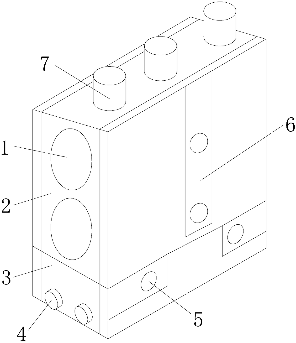
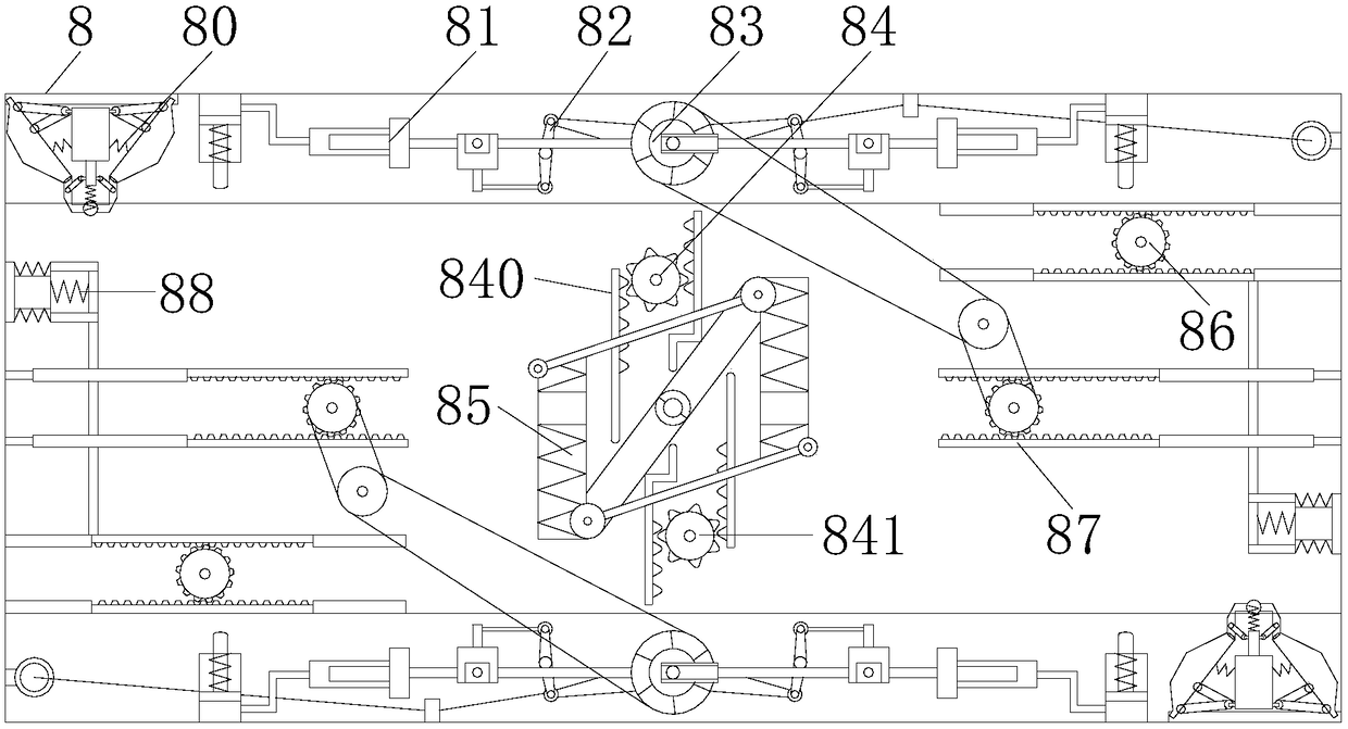
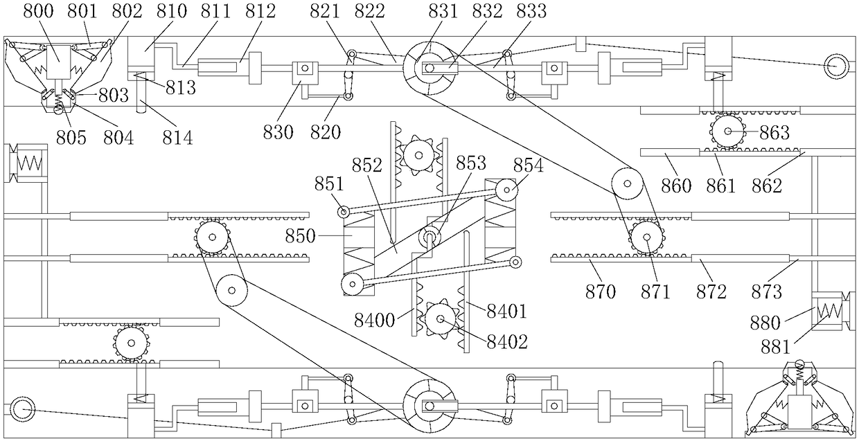
[0024] see Figure 1-3, the present invention provides a clamping mechanism technical solution suitable for pipeline transportation: its structure includes a pipe inlet 1, an outer frame body 2, a cover seat 3, a side plug 4, a single bolt hole 5, a double bolt hole 6, and a top plug 7 , the internal mechanism 8, the outer frame body 2 is provided with a pipe inlet 1, the outer frame body 2 is fixedly connected with the cover seat 3, and the two are formed int...


PUM


Abstract

The invention discloses a clamping mechanism suitable for pipeline transportation. The structure comprises inlet nozzles, an outer frame body, a cover seat, side plugs, single bolt holes, a double bolt hole, a top plug, and an internal mechanism; the outer frame body is provided with an inlet port, and the outer frame body and the cover seat are fixedly connected, and the two are formed into an integrated structure; the outer frame body and the cover seat are formed into an upper and lower structure, the cover seat is welded with side plugs, and the inlet pipes and the side plugs form a vertical mechanism. By means of the clamping mechanism suitable for pipeline transportation, pipelines at the same time in the opposite direction can be fed, and the feeding efficiency is high. The dampingdevice is used to assist the stability of the pipeline. The pneumatic inner rod is pushed up by the conveying movement and the two fixed shaft plates are locked to realize the fixing of the pneumaticinner rod, thereby further improving the stability of the pipeline transportation. During the conveying process, the pipeline presses two springs and two contact pressure collars to drive the lockingtooth plate to lock the two contact pressure collars. After the end of the conveying, the pneumatic inner rod fixes the two ends of the pipeline, and the two contact pressure collars fix the middle ofthe pipeline.

Description

technical field [0001] The invention relates to the field of pipeline transportation, in particular to a clamping mechanism suitable for pipeline transportation. Background technique [0002] A pipeline is a device connected by pipes, pipe connectors and valves to transport gas, liquid or fluid with solid particles; the pipeline must use a pipeline clamping device for auxiliary fixed transportation during the transportation process. [0003] The existing technology can’t feed into the pipeline at the same time in the opposite direction, the efficiency of pipe delivery is low, and the stability of pipeline transportation is poor. It is impossible to push up the pneumatic inner rod through the conveying movement and lock the two fixed shaft disks to realize the fixation of the pneumatic inner rod. The stability of pipeline transportation is improved; it is impossible to lock the two-part spring device and the two-part pressure-contact collar through the locking tooth plate dur...

Claims


Application Information

Patent Timeline
Patent Type & Authority Applications(China)
IPC IPC(8): B65D85/20B65D25/10B65D81/02
CPCB65D85/20B65D25/10B65D81/02
Inventor 孙伟鹏
Owner 孙伟鹏
Learn More