
Tube drawing mold

A technology of pipe drawing and drawing die, which is applied in the direction of wire drawing die, etc., can solve the problems of increasing the friction of the pipe blank, failing to meet the product precision requirements, and breaking the pipe blank, so as to reduce the drawing production cost, improve the quality, even force effect

Pending Publication Date: 2018-09-21
ZHEJIANG HAILIANG
View PDF0 Cites 1 Cited by
  • Summary
  • Abstract
  • Description
  • Claims
  • Application Information

AI Technical Summary

Problems solved by technology

[0002] The pipe drawing process refers to drawing the semi-finished pipe blank into a product with a certain size and cross-sectional shape through the drawing die. Most of the drawing devices currently used adopt the design of fixed installation of the die sleeve and the die to ensure that the drawing die can be used during the drawing process. It cannot be rotated during the drawing process. However, during the drawing process of the drawing die with such a structural design, that is, when the semi-finished product passes through the die, due to the eccentricity of the wall thickness of the tube blank, the position of the mold remains fixed, so the tube blank It can only be dragged between the moulds, which increases the friction on the tube blank and easily causes the tube blank to break
In addition, the finished product after passing through the mold will have uneven stress distribution, fail to meet product precision requirements, unstable quality, and high scrap rate

Method used


Image

  • Tube drawing mold

Examples


Embodiment Construction

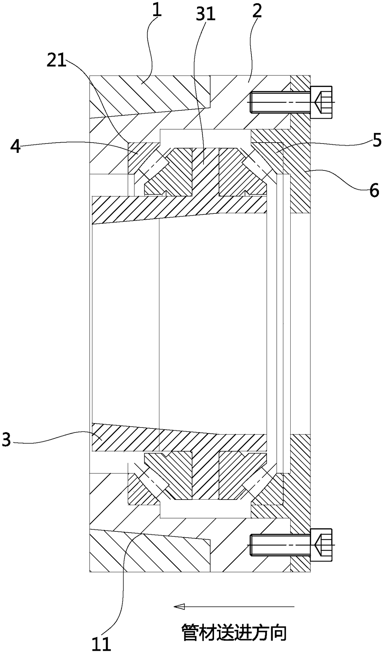
[0021] The invention discloses a drawing die, which includes a drawing die set and an inner die set, the inner die set is installed inside the drawing die set, the pipe drawing die also includes a bearing, and the bearing is installed on the between the inner die sleeve and the drawing die sleeve, so that the inner die sleeve can rotate under the action of circumferential stress difference. During the use of the drawing die, if the wall thickness of the incoming tube blank is not uniform, the circumferential stress difference caused by the different wall thickness of the tube blank will drive the inner mold sleeve around the drawing tube during the stretching process. The central axis of the mold sleeve rotates, and the sliding friction between the inner mold sleeve and the tube blank changes from sliding friction to rolling friction, so as to reduce the axial friction force on the tube blank during the drawing process, so that the force on the tube blank itself is more uniform...


PUM


Abstract

The invention discloses a tube drawing mold and belongs to the technical field of drawing. The technical problem that an eccentric billet is easy to break when used for drawing molds in the prior artis solved. The tube drawing mold disclosed by the invention comprises a drawing mold cover and an inner mold sleeve, wherein the inner mold sleeve is arranged on the inner side of the drawing mold cover; the tube drawing mold further comprises a bearing; the bearing is arranged between the inner mold sleeve and the drawing mold cover, so that the inner mold sleeve can rotate under the circumferential stress difference.

Description

【Technical field】 [0001] The invention relates to the technical field of drawing, in particular to a pipe drawing die. 【Background technique】 [0002] The pipe drawing process refers to drawing the semi-finished pipe blank into a product with a certain size and cross-sectional shape through the drawing die. Most of the drawing devices currently used adopt the design of fixed installation of the die sleeve and the die to ensure that the drawing die can be used during the drawing process. It cannot be rotated during the drawing process. However, during the drawing process of the drawing die with such a structural design, that is, when the semi-finished product passes through the die, due to the eccentricity of the wall thickness of the tube blank, the position of the mold remains fixed, so the tube blank It can only be dragged between the moulds, thereby increasing the friction force on the tube blank and easily causing the tube blank to break. In addition, the finished produ...

Claims


Application Information

Patent Timeline
IPC IPC(8): B21C3/02B21C1/22
CPCB21C1/22B21C3/02
Inventor 王云龙赵学龙蒋利荣朱张泉孙刚峰傅汉中
Owner ZHEJIANG HAILIANG
Learn More