Activated carbon adsorption tower system and desulfurization and denitration system

An activated carbon adsorption tower, adsorption tower technology, applied in gas treatment, membrane technology, dispersed particle separation and other directions, can solve the problems of large quantity, unimaginable impact and loss, difficult maintenance and repair, etc., to improve the denitration effect and improve the purification efficiency. , to avoid the effect of repeated processing

Active Publication Date: 2018-09-18
ZHONGYE-CHANGTIAN INT ENG CO LTD
View PDF4 Cites 2 Cited by
  • Summary
  • Abstract
  • Description
  • Claims
  • Application Information

AI Technical Summary

Problems solved by technology

In addition, the round roller feeder often fails during the production process, such as: material leakage when the flue gas pressure changes, and the material cannot be controlled when the machine is stopped.
In addition, the number of round roller feeders is large (as long as one fails, the entire large-scale device has to be shut down), the cost is high, and maintenance is difficult, so it has brought certain restrictions on the development of activated carbon technology.
[0012] Secondly, for the feeding rotary valve in the prior art, there are the following problems: For the transportation of fragile particles such as desulfurization and denitrification activated carbon, the use of rotary valves on the one hand ensures the airtightness of the tower body, and on the other hand realizes the material flow. Transport without damage, but if the conveying medium is sheared due to the rotation of the blades during the conveying process of the rotary valve, see attached Figure 9 , will cause an increase in system operating costs
For a large adsorption tower usually with a height of about 20 meters, the failure of the round roller feeder or the rotary valve during the production process will cause huge losses to the continuous operation of the process, because the adsorption tower is filled with several tons of activated carbon , it is quite difficult to manually dismantle and repair or reinstall, and the impact and loss caused by shutdown are unimaginable

Method used


Image

  • Activated carbon adsorption tower system and desulfurization and denitration system
  • Activated carbon adsorption tower system and desulfurization and denitration system
  • Activated carbon adsorption tower system and desulfurization and denitration system

Examples


Embodiment approach

[0093] According to the first embodiment provided by the present invention, an activated carbon adsorption tower system is provided.

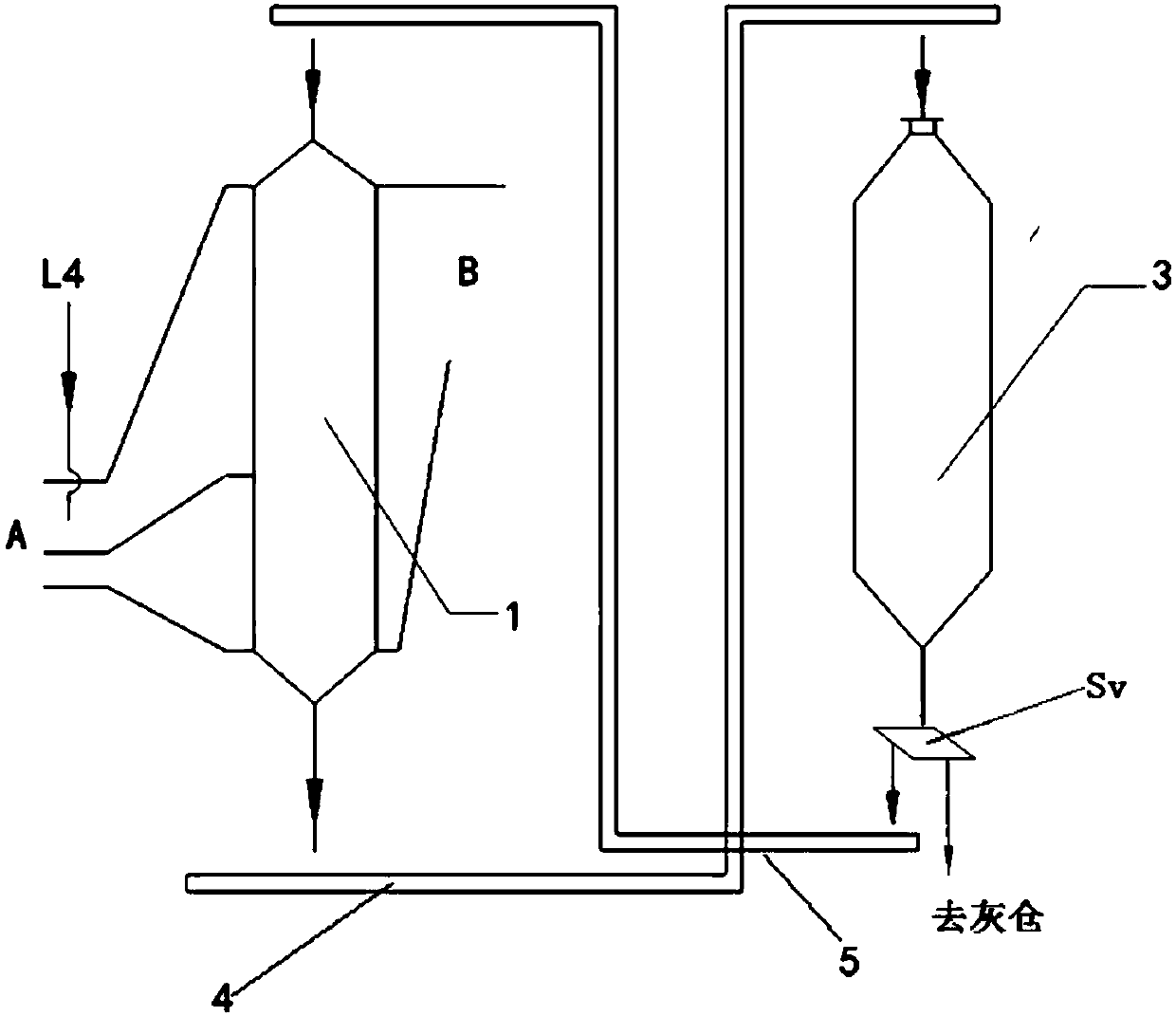
[0094] An activated carbon adsorption tower system. One side of the activated carbon adsorption tower 1 is provided with a first flue gas inlet A and a second flue gas inlet B. The other side of the adsorption tower 1 is provided with a first flue gas outlet C and a second flue gas outlet D. The first flue gas inlet A is arranged below the second flue gas inlet B. The first flue gas outlet C is arranged below the second flue gas outlet D. The first flue gas inlet A is connected to the original flue gas delivery pipe L1. The first flue gas outlet C is connected to the second flue gas inlet B through the first delivery pipe L2. The second flue gas outlet D is connected to the clean flue gas pipe L3. A first ammonia injection device 201 is provided at the first flue gas inlet A. A second ammonia injection device 202 is provided at the second flu...

Embodiment 1

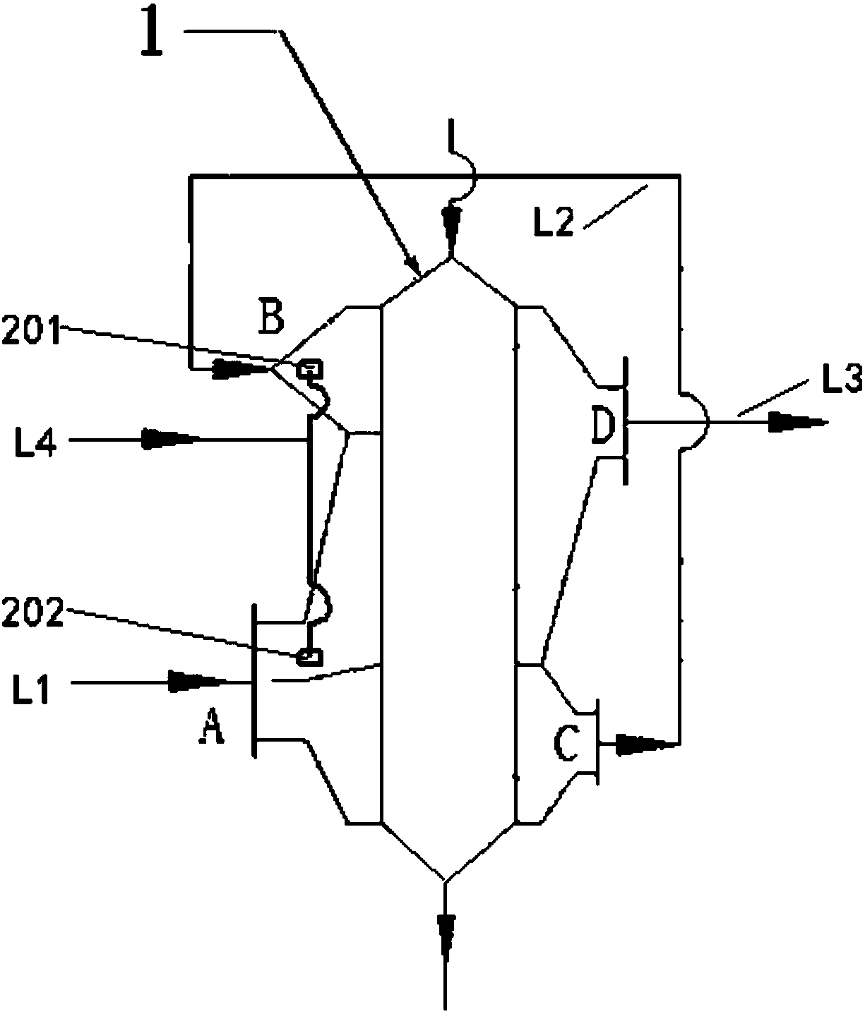
[0108] Such as figure 2 As shown, an activated carbon adsorption tower system is provided with a first flue gas inlet A and a second flue gas inlet B on one side of the activated carbon adsorption tower 1. The other side of the adsorption tower 1 is provided with a first flue gas outlet C and a second flue gas outlet D. The first flue gas inlet A is arranged below the second flue gas inlet B. The first flue gas outlet C is arranged below the second flue gas outlet D. The first flue gas inlet A is connected to the original flue gas delivery pipe L1. The first flue gas outlet C is connected to the second flue gas inlet B through the first delivery pipe L2. The second flue gas outlet D is connected to the clean flue gas pipe L3. A first ammonia injection device 201 is provided at the first flue gas inlet A. A second ammonia injection device 202 is provided at the second flue gas inlet B. Both the first ammonia injection device 201 and the second ammonia injection device 202 ...

Embodiment 2

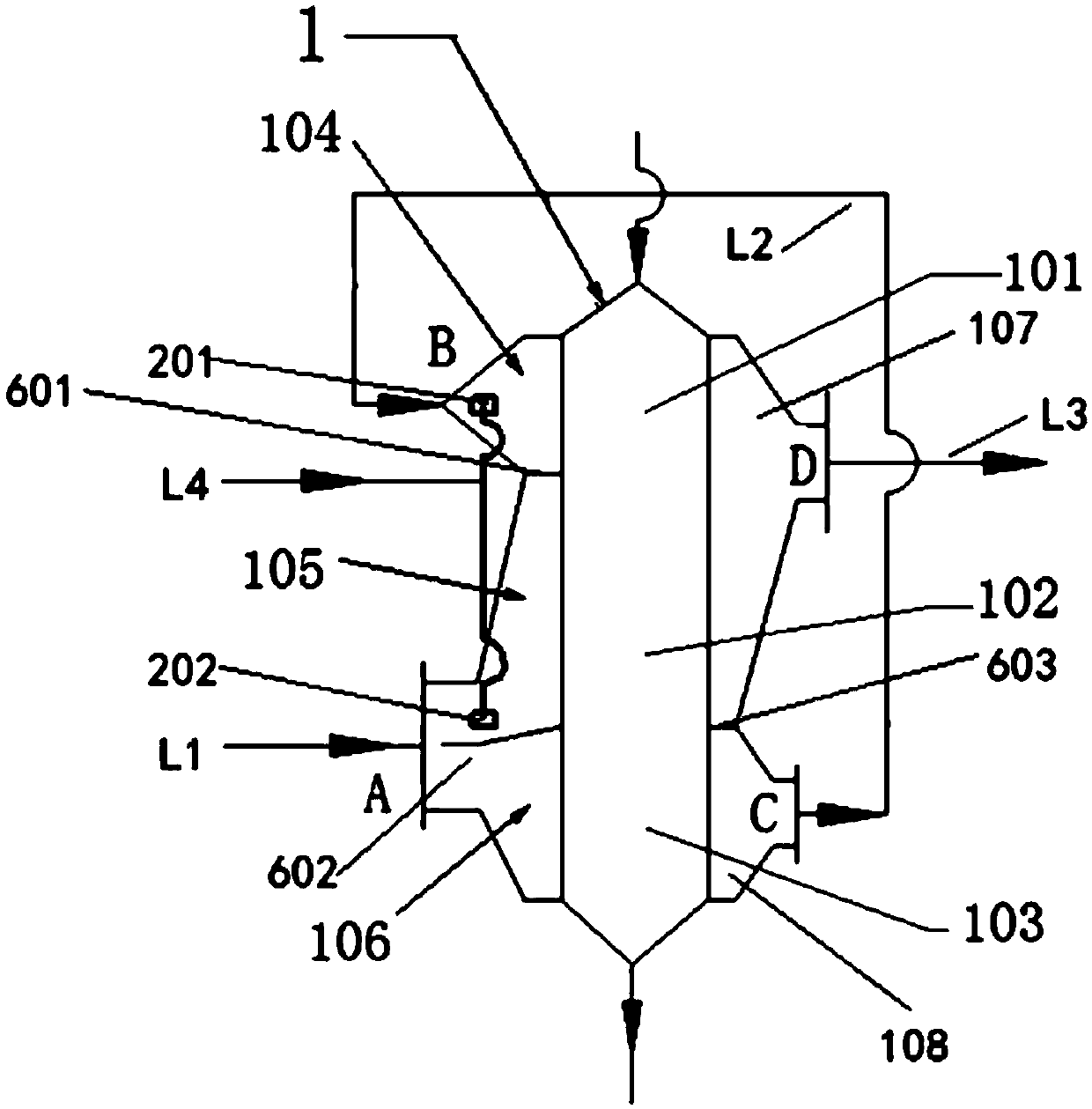
[0112] Such as image 3 As shown, Example 1 is repeated, except that the position of the upper part 104 of the intake flue corresponding to the activated carbon adsorption tower 1 is the upper part 101 of the adsorption tower. The position of the middle part 105 of the intake flue corresponding to the activated carbon adsorption tower 1 is the middle part 102 of the adsorption tower. The position of the lower part 106 of the intake flue corresponding to the activated carbon adsorption tower 1 is the lower part 103 of the adsorption tower. A first partition 601 is provided between the first flue gas inlet A and the second flue gas inlet B (that is, a first partition 601 is provided between the upper portion 104 of the intake flue and the middle portion 105 of the intake flue). A second partition 602 is provided between the middle portion 105 of the intake flue and the lower portion 106 of the intake flue. A third partition 603 is arranged between the first flue gas outlet C and...


PUM


Abstract

An activated carbon adsorption tower system is disclosed. One side of an activated carbon adsorption tower is provided with a first flue gas inlet and a second flue gas inlet. The other side of the adsorption tower is provided with a first flue gas outlet and a second flue gas outlet. The first flue gas inlet is disposed below the second flue gas inlet. The first flue gas outlet is disposed belowthe second flue gas outlet. The first flue gas inlet is connected to an original flue gas conveying pipe. The first flue gas outlet is connected to the second flue gas inlet through a first delivery pipe. The second flue gas outlet is connected to a clean flue gas pipe. Both a first ammonia injection device and a second ammonia injection device are connected to a mixed gas delivery pipe. The activated carbon adsorption tower system adsorbs original flue gas into different parts of the adsorption tower through a pipeline or a separator, and is beneficial to the full utilization of activated carbon, and the denitration rate of the system is improved.

Description

Technical field [0001] The invention relates to an activated carbon method flue gas purification device, which belongs to an activated carbon method flue gas purification device suitable for air pollution control, in particular an activated carbon adsorption tower system and a desulfurization and denitrification system for the purification of sintering flue gas, and relates to the environment Protect the field. Background technique [0002] For industrial flue gas, especially sintering machine flue gas in the iron and steel industry, it is ideal to use desulfurization and denitrification devices and processes including activated carbon adsorption towers and desorption towers. In the desulfurization and denitrification devices including activated carbon adsorption tower and desorption tower (or regeneration tower), the activated carbon adsorption tower is used to adsorb sulfur oxides and nitrogen from sintering flue gas or exhaust gas (especially the sintering flue gas of sinterin...

Claims


Application Information

Patent Timeline
Patent Type & Authority Applications(China)
IPC IPC(8): B01D53/76B01D53/60B01D53/70B01D53/02
CPCB01D53/02B01D53/60B01D53/70B01D53/76B01D2251/2062B01D2257/2064
Inventor 魏进超李俊杰康建刚
Owner ZHONGYE-CHANGTIAN INT ENG CO LTD
Why Eureka
Try Eureka