Interphone convenient to fixedly place
A walkie-talkie, convenient technology, applied in the direction of electrical components, transmission systems, etc., can solve the problems of easy toppling, inconvenient for fixed placement, etc., to achieve the effect of easy protection, simple structure, and increased stability
- Summary
- Abstract
- Description
- Claims
- Application Information
AI Technical Summary
Problems solved by technology
Method used
Image
Examples
Embodiment 1
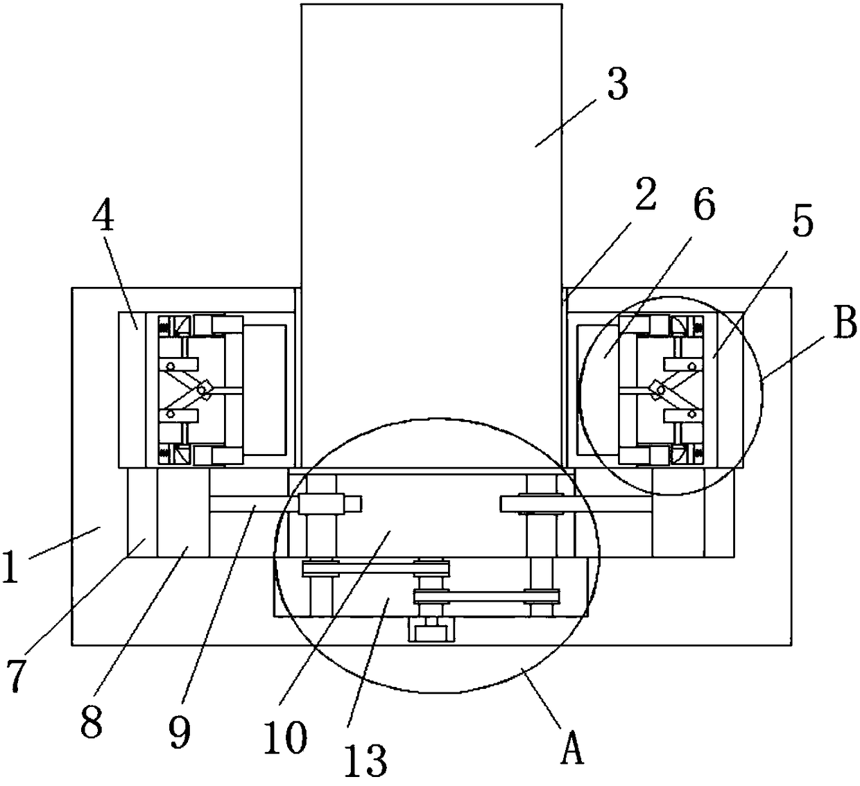
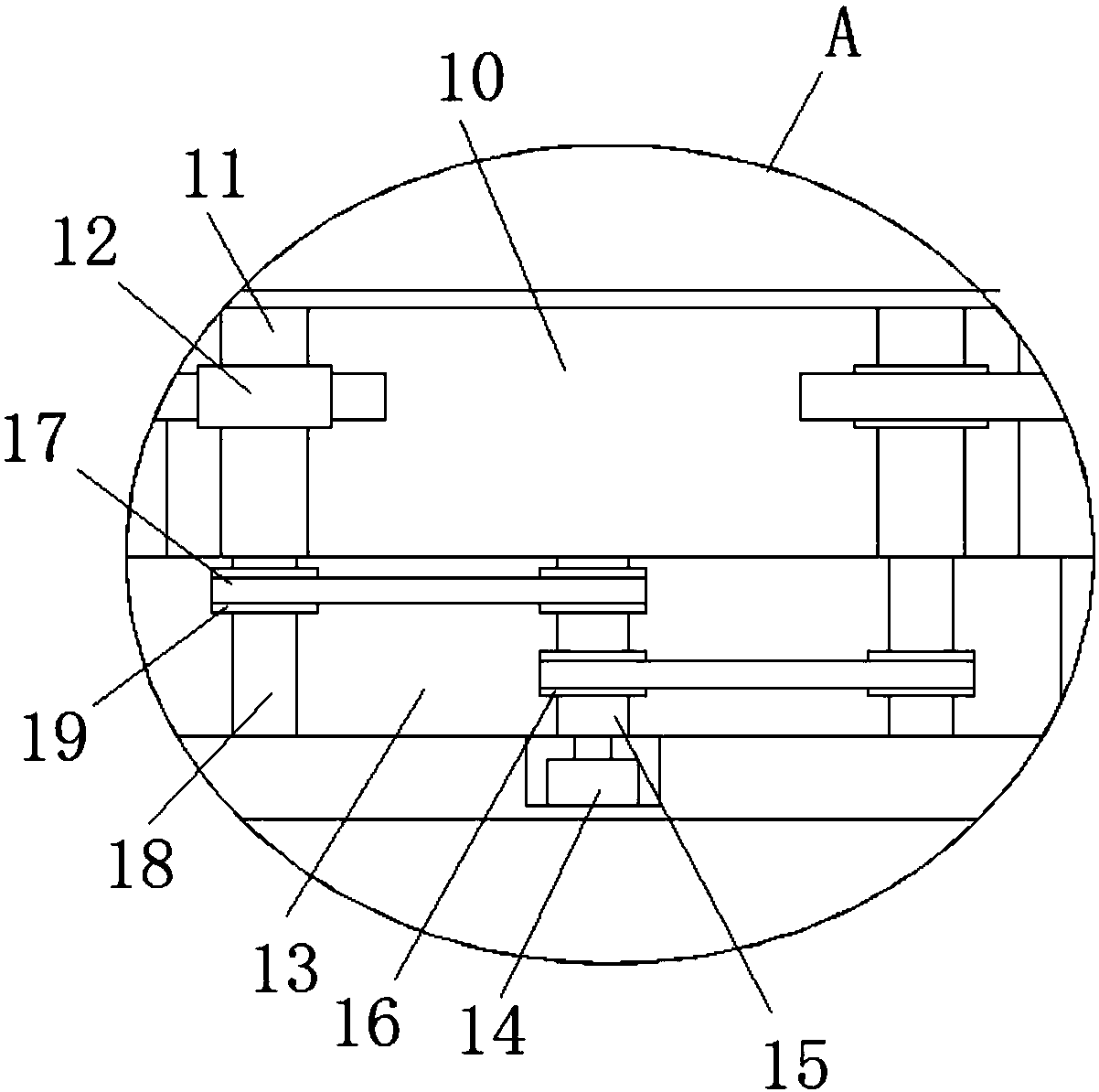
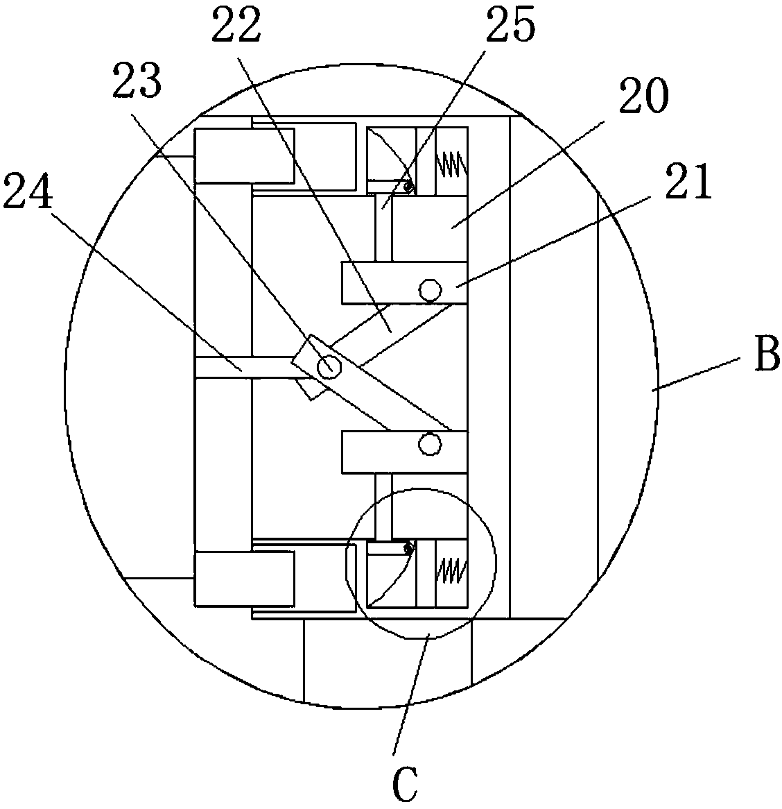
[0025] refer to Figure 1-5In this embodiment, a walkie-talkie that can be fixedly placed is proposed, including a fixed seat 1, a fixed groove 2 is opened on the top of the fixed seat 1, and a walkie-talkie body 3 is movably installed in the fixed groove 2, and the fixed groove 2 is used to place the walkie-talkie body 3. There are moving grooves 4 on the inner walls of both sides of the fixed groove 2, and a moving plate 5 is slidably installed in the moving groove 4, and a clamping plate 6 is slidably installed on the side where the two moving plates 5 are close to each other. 5 drives the clamping plate 6 to move, the two clamping plates 6 are compatible with the walkie-talkie body 3, the two-way radio body 3 is clamped by the clamping plate 6, and the bottom inner wall of the moving groove 4 is provided with a groove 7, A slide plate 8 is slidably installed in the groove 7, and the tops of the two slide plates 8 are respectively fixedly connected with the bottoms of the t...
Embodiment 2
[0027] One side of the extruding plate 30 is rotatably equipped with a runner, and the runner is rollingly connected with the corresponding arc-shaped plate 29. The sides of the two moving plates 5 that are close to each other are provided with two rectangular grooves, and the two clamping plates 6 Two rectangular blocks are fixedly installed on the side far away from each other, and the rectangular block is slidably connected with the side wall of the corresponding rectangular groove. The top inner wall of the moving groove 4 is welded with a slide rail, and the top of the moving plate 5 is fixedly installed with a Sliding block, sliding block is slidably connected with the corresponding slide rail, rotating motor 14 is installed on the fixed seat 1, the output shaft of rotating motor 14 is fixedly connected with the bottom of rotating rod 15, and the bottom inner wall of rotating groove 13 is provided with placement groove, The rotary motor 14 is fixedly installed on the bott...
Embodiment 3
[0029] One side of the extruding plate 30 is rotatably equipped with a runner, and the runner is rollingly connected with the corresponding arc-shaped plate 29. The sides of the two moving plates 5 that are close to each other are provided with two rectangular grooves, and the two clamping plates 6 Two rectangular blocks are fixedly installed on the side far away from each other, and the rectangular block is slidably connected with the side wall of the corresponding rectangular groove. The top inner wall of the moving groove 4 is welded with a slide rail, and the top of the moving plate 5 is fixedly installed with a Sliding block, sliding block is slidably connected with the corresponding slide rail, rotating motor 14 is installed on the fixed seat 1, the output shaft of rotating motor 14 is fixedly connected with the bottom of rotating rod 15, and the bottom inner wall of rotating groove 13 is provided with placement groove, The rotating motor 14 is fixedly installed on the bo...
PUM
 Abstract
Description
Claims
Application Information
 - R&D
- Intellectual Property
- Life Sciences
- Materials
- Tech Scout
- Unparalleled Data Quality
- Higher Quality Content
- 60% Fewer Hallucinations
Browse by: Latest US Patents, China's latest patents, Technical Efficacy Thesaurus, Application Domain, Technology Topic, Popular Technical Reports.
© 2025 PatSnap. All rights reserved.Legal|Privacy policy|Modern Slavery Act Transparency Statement|Sitemap|About US| Contact US: help@patsnap.com


