Preparation method of multilayer-film X-ray zone plate
A technology of zone plate and multi-layer film, which is applied in the field of preparation of multi-layer film X-ray zone plate, can solve the problems of long polishing time, high cost, and small roughness of the section of the zone plate, so as to facilitate mobile operation, The effect of cutting cost reduction and wide application prospect
- Summary
- Abstract
- Description
- Claims
- Application Information
AI Technical Summary
Problems solved by technology
Method used
Image
Examples
Embodiment 1
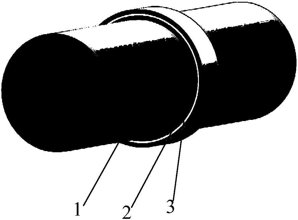
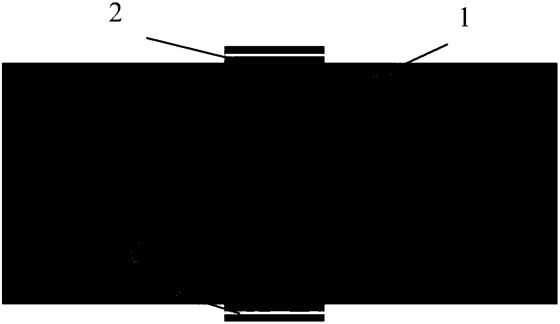
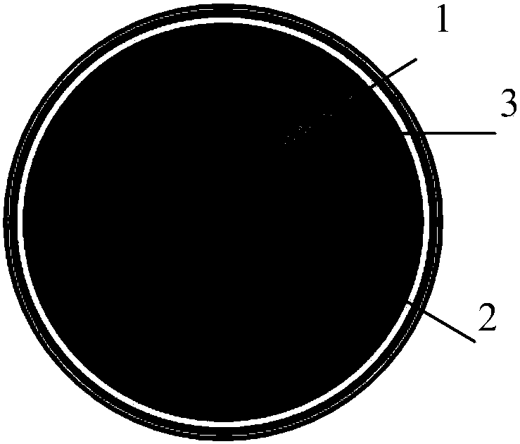
[0035] First, according to the designed height of the zone plate, the central filament as the main support of the zone plate: the side surface of the tungsten wire is selectively shielded, such as Figure 4 As shown, 4 in the figure is an occluder. The length of each unshielded tungsten wire is slightly longer than the designed height of the zone plate. Subsequently, the atomic layer deposition method is used to alternately deposit aluminum oxide films and hafnium oxide films on the surface of the tungsten wire, that is, deposit a layer of aluminum oxide films first, and then deposit a layer of hafnium oxide films, so that the two films are deposited alternately in sequence, as Figure 5 As shown, 5 in the figure is a multilayer film of two materials, which constitutes the annular structure of the zone plate. The thickness of each film decreases in the radial direction according to the design requirements of the zone plate. For X-rays with a wavelength of 0.15nm, For a zone p...
Embodiment 2
[0037]First, according to the designed height of the zone plate, the central filament as the main support of the zone plate: the side surface of the gold wire is selectively blocked, such as Figure 4 As shown, 4 in the figure is an occluder. The length of each unshielded gold wire is slightly greater than the designed height of the zone plate. Subsequently, the magnetron sputtering method is used to alternately deposit aluminum oxide films and iridium films on the surface of the gold wire, that is, deposit a layer of aluminum oxide films first, and then deposit a layer of iridium films, so that the two films are deposited alternately in sequence, as Figure 5 As shown, 5 in the figure is a multilayer film of two materials, which constitutes the annular structure of the zone plate. The thickness of each layer of film decreases in the radial direction according to the design requirements of the zone plate. For X-rays with a wavelength of 0.1nm, For a zone plate with a focal le...
Embodiment 3
[0039] First, according to the designed height of the zone plate, the central filament as the main support of the zone plate: the side surface of the silver wire is selectively blocked, such as Figure 4 As shown, 4 in the figure is an occluder. The length of each unshielded silver wire is slightly greater than the designed height of the zone plate. Subsequently, the laser deposition method is used to alternately deposit aluminum oxide films and tantalum oxide films on the surface of the silver wire, that is, deposit a layer of aluminum oxide films first, and then deposit a layer of tantalum oxide films, so that the two films are deposited alternately in sequence, as shown in Fig. Figure 5 As shown, 5 in the figure is a multilayer film of two materials, which constitutes the annular structure of the zone plate. The thickness of each layer of film decreases in the radial direction according to the design requirements of the zone plate. For X-rays with a wavelength of 0.05nm, ...
PUM
| Property | Measurement | Unit |
|---|---|---|
| width | aaaaa | aaaaa |
Abstract
Description
Claims
Application Information
 - R&D
- Intellectual Property
- Life Sciences
- Materials
- Tech Scout
- Unparalleled Data Quality
- Higher Quality Content
- 60% Fewer Hallucinations
Browse by: Latest US Patents, China's latest patents, Technical Efficacy Thesaurus, Application Domain, Technology Topic, Popular Technical Reports.
© 2025 PatSnap. All rights reserved.Legal|Privacy policy|Modern Slavery Act Transparency Statement|Sitemap|About US| Contact US: help@patsnap.com


