Device and method for testing gas permeability of concrete

A technology of gas permeability and testing equipment, which is applied in the direction of measuring equipment, permeability/surface area analysis, suspension and porous material analysis, etc. It can solve the problem of large measurement error, poor evaluation of concrete impermeability coefficient, and complex device structure and other problems, to achieve the effect of high accuracy of results, accurate and reliable measurement results, and simple measurement process

Pending Publication Date: 2018-09-14
AIR FORCE UNIV PLA +1
View PDF12 Cites 1 Cited by
  • Summary
  • Abstract
  • Description
  • Claims
  • Application Information

AI Technical Summary

Problems solved by technology

However, the existing air pressure difference measurement method and device structure is complex, the measurement error is large, and the concrete impermeability coefficient cannot be well evaluated.

Method used


Image

  • Device and method for testing gas permeability of concrete
  • Device and method for testing gas permeability of concrete

Examples


Embodiment 1

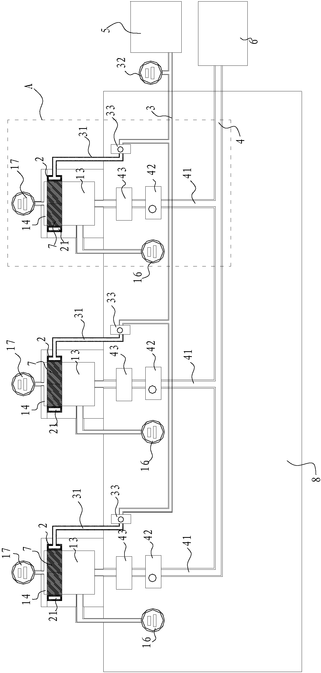
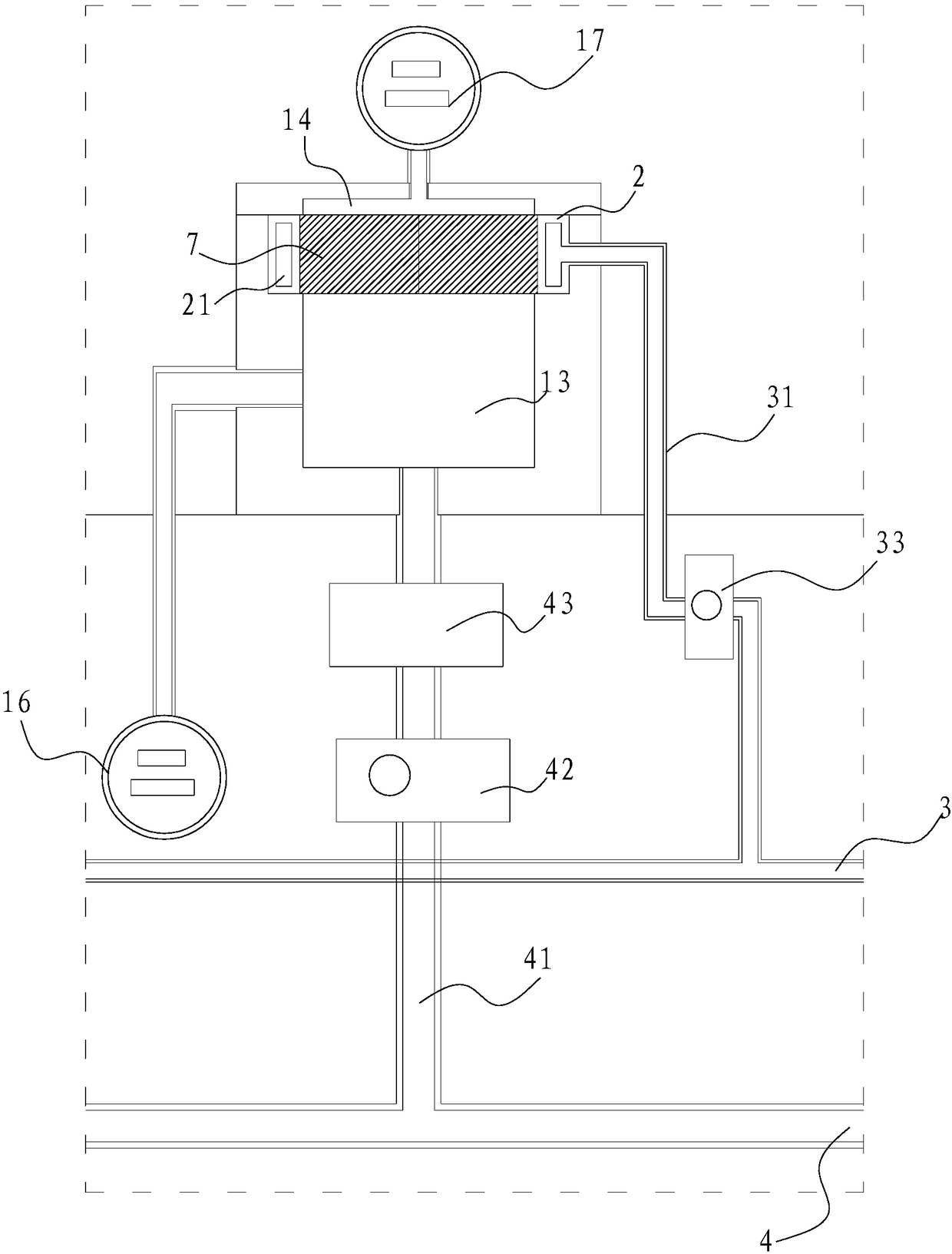
[0044] Such as figure 1 As shown, a concrete gas permeability testing device includes a test box 1, an elastic sealing ring 2 for fixing a concrete specimen 7, a pressurizing pump 5 and a pressure tank 6, and the elastic sealing ring 2 is arranged on the test box 1 on the inner wall, the elastic sealing ring 2 is provided with an annular cavity 21 coaxial with it; into a first cavity 13 and a second cavity 14 that are independent of each other, the booster pump 5 is connected to the elastic sealing ring 2 through the first pipeline 3 and communicates with the annular cavity 21, the pressure tank 6 is connected and communicated with the first chamber 13 through the second pipeline 4, and the second chamber 14 is communicated with the atmosphere. In this embodiment, by installing an elastic sealing ring in the test box, the concrete specimen can be installed in the elastic sealing ring, and the annular cavity in the elastic sealing ring is pressurized by a pressurizing pump, so...

Embodiment 2

[0056] A kind of method that adopts the test device of embodiment 1 to concrete specimen permeability is tested, comprises the following steps:

[0057] S1, the concrete test piece is packed in the elastic sealing ring, adds confining pressure to the annular cavity of the elastic sealing ring by a booster pump, so that the inner ring wall of the elastic sealing ring compresses the peripheral edge of the concrete test piece;

[0058] S2, the inert gas stored in the pressure tank is pressed at the preset inlet pressure P i Lead into the first cavity, so that the inert gas in the first cavity passes through the concrete specimen in a one-way permeable mode and enters the second cavity;

[0059] S3, after the intake pressure is stabilized, stop intake;

[0060] S4, after the Δt time, record the air pressure P in the first chamber f ;

[0061] S5, calculating and obtaining the permeability coefficient of the concrete specimen according to the air pressure change.

[0062] The c...


PUM


Abstract

The invention relates to a device and a method for testing the gas permeability of concrete. The device comprises test boxes, elastic sealing rings, a pressure pump and a pressure tank. The elastic sealing rings are used for fixing concrete test pieces and are arranged on the inner walls of the test boxes in a surrounding manner, and annular cavities which are coaxial with the elastic sealing rings are arranged in the elastic sealing rings; the concrete test pieces are fittingly mounted in the elastic sealing rings, inner cavities of the test boxes are divided into first cavities and second cavities by the concrete test pieces, the first cavities are independent from the second cavities, the pressure pump is connected with the elastic sealing rings by a first pipeline and is communicated with the annular cavities, the pressure tank is connected and communicated with the first cavities by a second pipeline, and the second cavities are communicated with the atmosphere. The device and themethod have the advantages that gaps between the concrete test pieces and the elastic sealing rings can be prevented, inert gas in the first cavities only can be unidirectionally permeated into the external atmosphere via the concrete test pieces when the first cavities under the concrete test pieces are filled with the inert gas via the pressure tank, measurement procedures are simple, and results are high in accuracy.

Description

technical field [0001] The invention relates to the technical field of concrete testing, in particular to a concrete gas permeability testing device and method. Background technique [0002] The permeability of concrete directly affects the durability of concrete. The deterioration of the durability of concrete is essentially caused by the corrosive medium in the environment entering the interior of the concrete through transmission channels such as pores or micro-cracks. The difficulty of transmission in concrete, therefore, the anti-permeability of concrete is recognized as an important evaluation index of concrete durability. Concrete permeability testing methods currently include water infiltration method, ion infiltration method and gas infiltration method. Croatian scholar Calogovic proposed the air pressure difference method with time as a variable. The principle of this method is to apply a pressure different from the environment in a closed container, and calculate...

Claims


Application Information

Patent Timeline
Patent Type & Authority Applications(China)
IPC IPC(8): G01N7/10G01N15/08
CPCG01N7/10G01N15/0826
Inventor 吴永根刘庆涛刘军忠于洪江陈俊良
Owner AIR FORCE UNIV PLA
Why Eureka
Try Eureka