
Device for sponge sheet machining

A technology of sponge sheet and equipment, applied in metal processing and other directions, can solve the problems of low production efficiency, high cost, not satisfying continuous processing, etc., and achieve the effect of high slicing efficiency and consistent thickness

Inactive Publication Date: 2018-09-14
重庆致昌塑胶制品有限公司
View PDF0 Cites 1 Cited by
  • Summary
  • Abstract
  • Description
  • Claims
  • Application Information

AI Technical Summary

Problems solved by technology

[0003] Among them, when the sponge is used in the automobile shock absorption system, it is usually necessary to use a sheet-shaped sponge for subsequent processing. There are two ways to produce a sheet-shaped sponge. One is to cut a large piece of sponge into a sheet, and the other is to use a specific model to develop Sponge is made of foam, the latter process is more complicated, and the cost is relatively high, so using a slicing mechanism to slice a large sponge is currently the main processing method
[0004] When cutting the sponge in the prior art, because the sponge is easy to deform and is not easy to fix, usually the sponge piece is removed after one piece is cut, and then the next piece of sponge is cut, the production efficiency is low, and it does not meet the requirements of continuous processing

Method used


Image

  • Device for sponge sheet machining
  • Device for sponge sheet machining

Examples


Embodiment Construction

[0026] Further detailed explanation through specific implementation mode below:

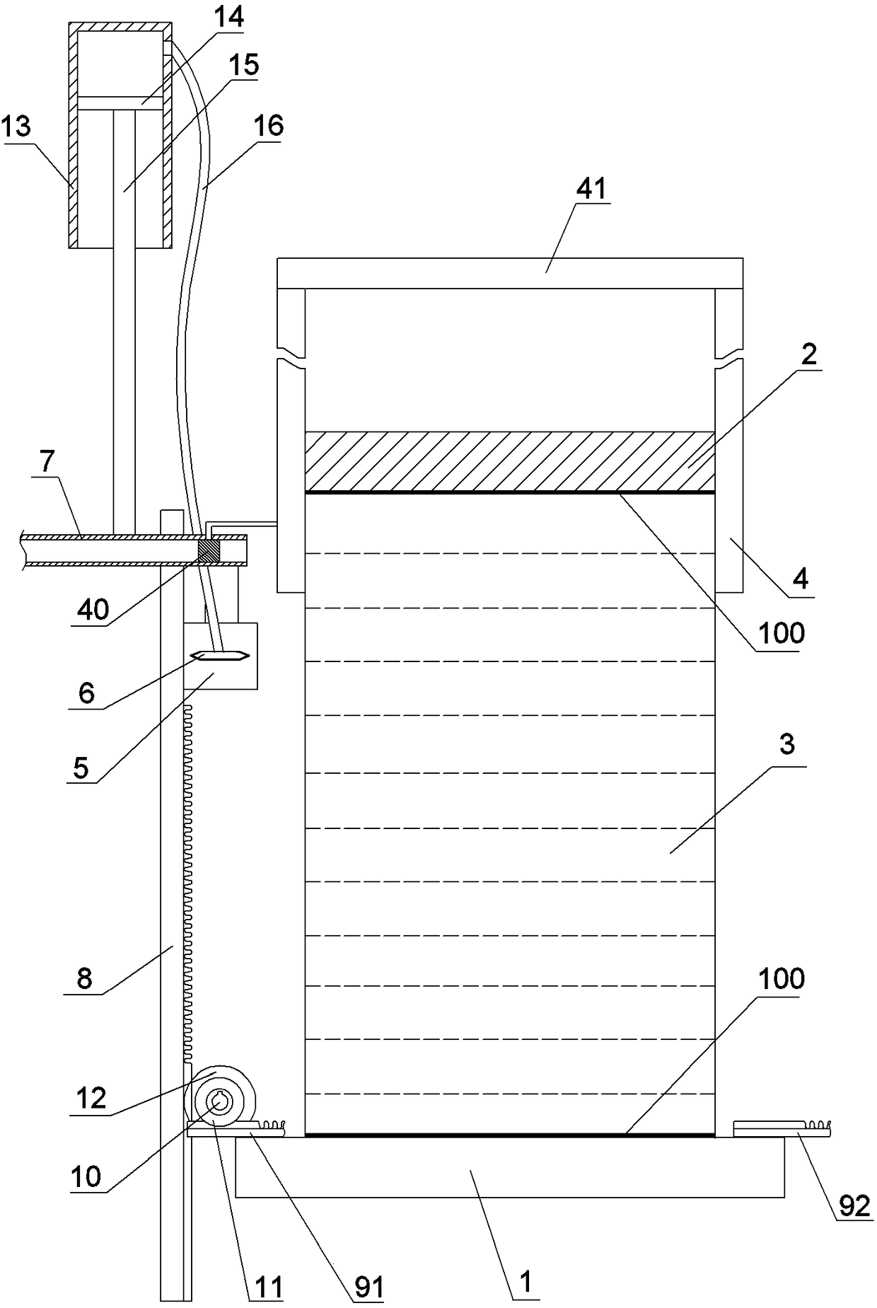
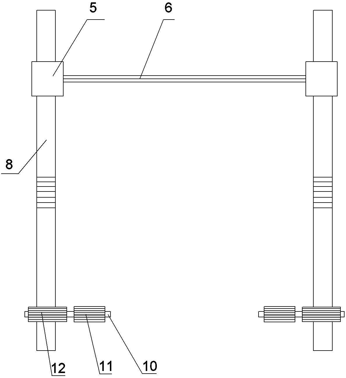
[0027] The reference signs in the drawings of the description include: support plate 1, limit plate 2, sponge block 3, baffle plate 4, block 40, connecting plate 41, sliding seat 5, cutter 6, chute 7, vertical teeth Bar 8, first transverse rack 91, second transverse rack 92, rotating shaft 10, first gear 11, second gear 12, piston chamber 13, piston 14, piston rod 15, hose 16, serrated anti-skid layer 100.

[0028] Such as figure 1 with figure 2 As shown, a kind of sponge sheet processing equipment of the present embodiment includes a frame on which a cutting mechanism is vertically slidably connected. Cutter 6, the cutter 6 is a double-edged knife, the inside of the cutter 6 is hollow, the cutter 6 is provided with a plurality of air suction ports, and one of the sliding seats 5 is fixedly connected with a transverse chute 7.

[0029] A support plate 1 is slidably arranged on the frame below...


PUM


Abstract

The invention belongs to the field of sponge machining, and particularly discloses a device for sponge sheet machining. The device comprises a rack, and a cutting mechanism is slidably connected to the rack, wherein the cutting mechanism comprises sliding seats and a hollow cutter, and multiple exhaust inlets are formed in the cutter; a piston cavity is fixed to the rack, a piston is slidably connected in the piston cavity, a piston rod is fixedly connected to the piston, the piston rod is fixedly connected with the sliding seats, and the piston cavity communicates with the hollow cutter through a hose; a supporting plate is slidably arranged on the portion, below the cutting mechanism, of the rack, a limiting plate is detachably connected to the supporting plate, the limiting plate is located above the cutting mechanism, the upper surface of the supporting plate and the lower surface of the limiting plate are each provided with an anti-skid layer, and baffles are vertically and slidably connected to the side walls of the limiting plate separately; and each sliding seat is provided with a clamping part, clamping matching parts which are matched with the clamping parts are fixedly connected to the baffles, and a transmission mechanism is connected between the supporting plate and the cutting mechanism. By means of the device for sponge sheet machining, the sponge slicing efficiency can be improved.

Description

technical field [0001] The invention relates to the field of sponge processing, in particular to equipment for processing sponge sheets. Background technique [0002] Sponge rubber is a porous structure material with pores throughout the material. It has low density, excellent elasticity and flexibility, and has high shock absorption, sound insulation and heat insulation properties. Its products are of various types and shapes, and are widely used in many aspects such as sealing, shock absorption, noise reduction, heat insulation, clothing, shoemaking, home appliances, printing and dyeing, fitness equipment and ion exchange. [0003] Among them, when the sponge is used in the automobile shock absorption system, it is usually necessary to use a sheet-shaped sponge for subsequent processing. There are two ways to produce a sheet-shaped sponge. One is to cut a large piece of sponge into a sheet, and the other is to use a specific model to develop Sponge is made of foam, the l...

Claims


Application Information

Patent Timeline
Patent Type & Authority Applications(China)
IPC IPC(8): B26D1/02B26D7/02B26D7/08B26D7/26
CPCB26D1/02B26D7/025B26D7/088B26D7/2628
Inventor 彭军
Owner 重庆致昌塑胶制品有限公司
Learn More