A foam generation method using liquid nitrogen and its application and fire extinguishing method

A generation method and technology of foam, applied in fire rescue and other fields, can solve the problems of limited gas supply of gas compressors and compressed gas cylinders, no space for layout, and large space occupation, so as to facilitate on-site layout and fire extinguishing work, The effect of strong independent working ability and small footprint

Active Publication Date: 2021-04-23
CHINA PETROLEUM & CHEM CORP +1
View PDF7 Cites 0 Cited by
  • Summary
  • Abstract
  • Description
  • Claims
  • Application Information

AI Technical Summary

Problems solved by technology

Among them, compressed gas foam fire extinguishing usually uses gas compressors, high-pressure gas pipe networks or compressed gas cylinders for gas supply, and the gas supply of gas compressors and compressed gas cylinders is limited, which cannot meet the needs of large flow, high pressure, and long-term supply. Gas requirements, and most places do not have high-pressure gas pipeline network
However, if large flow, high pressure, and long-term gas supply are required, multiple compressors or compressed gas cylinders need to be installed (for example, a foam fire engine with a flow rate of 150L / S, the gas supply flow rate should be at least 1050L / S s, its gas supply needs to be supplied by multiple large air compressors), it takes up a lot of space, and there is often no space for layout in the oil depot tank area and equipment area, which is not conducive to on-site layout
[0003] Another type of gas storage foam fire extinguishing usually stores compressed gas in the fire extinguishing agent container. When a large flow rate is sprayed, the compressed gas will be consumed in large quantities. Gas, and in the state of large-flow injection, the air compressor and compressed gas cylinder alone cannot guarantee sufficient supply of compressed gas, resulting in the inability to effectively meet the requirements of high-pressure injection. As the injection continues, the pressure in the container decreases significantly. The performance of the foam gradually deteriorates, which affects the fire extinguishing effect
When extinguishing a major fire, it is necessary to produce large-flow high-expansion foam for fire extinguishing. At this time, the flow rate of the foam mixture increases, and the gas supply volume of the compressed gas also needs to increase accordingly. However, the existing gas supply method cannot achieve high-flow high-pressure compression. For the supply of gas, the maximum foam mixture flow rate of the current compressed gas foam fire truck is only 15-20L / s. Application in tank fires or large-scale ground flow fires

Method used


Image

  • A foam generation method using liquid nitrogen and its application and fire extinguishing method
  • A foam generation method using liquid nitrogen and its application and fire extinguishing method
  • A foam generation method using liquid nitrogen and its application and fire extinguishing method

Examples


Embodiment 1

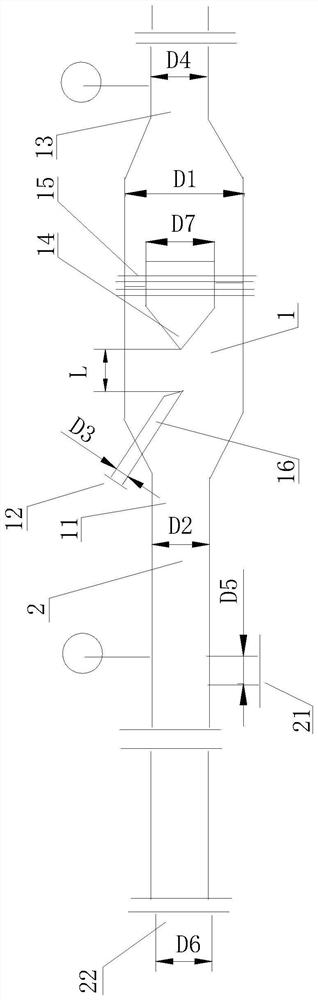
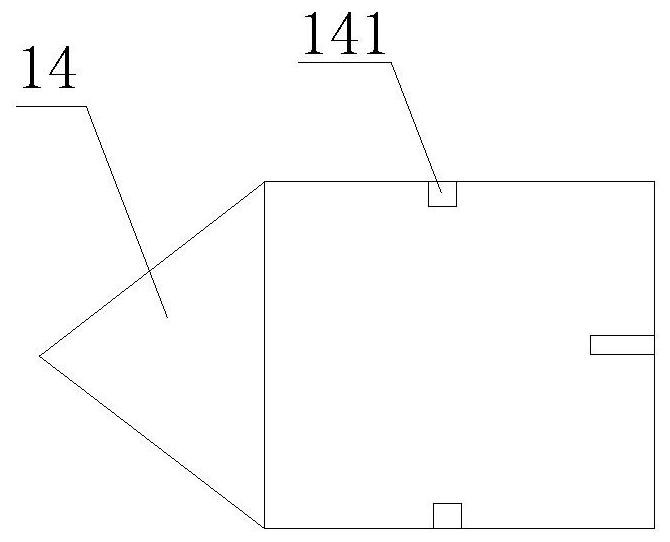
[0059] use figure 1 The mixing device shown mixes to generate foam, wherein the mixing device has a mixing chamber for mixing liquid nitrogen and foam mixture, and the wall of the mixing chamber is provided with a foam stock solution inlet, a liquid nitrogen inlet and a The foam outlet, the foam outlet and the foam mixed liquid inlet are respectively located at two ends of the cylindrical structure. The relationship between the diameter D2 of the foam mixture inlet and the diameter D3 of the gas inlet is: D2 / D3=8, the relationship between the diameter D1 of the cylindrical structure and the diameter D2 of the foam stock solution inlet is: D1 / D2=1.4, The relationship between the diameter D1 of the cylindrical structure and the diameter D4 of the foam outlet is: D1 / D4=1.2, a spoiler is arranged in the mixing chamber, and the spoiler is formed as figure 2 As shown in the conical structure, the conical top of the conical structure faces the foaming material inlet, the cross-sect...

Embodiment 2

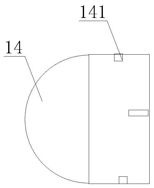
[0063] use figure 1 The mixing device shown mixes to generate foam, wherein the mixing device has a mixing chamber for mixing liquid nitrogen and foam mixture, and the wall of the mixing chamber is provided with a foam mixture inlet, a liquid nitrogen inlet and a A foam outlet, the foam outlet and the foam mixture inlet are respectively located at two ends of the cylindrical structure. The relationship between the diameter D2 of the foam mixture inlet and the diameter D3 of the gas inlet is: D2 / D3=10, the relationship between the diameter D1 of the cylindrical structure and the diameter D2 of the foam stock solution inlet is: D1 / D2=2, The relationship between the diameter D1 of the cylindrical structure and the diameter D4 of the foam outlet is: D1 / D4=1.2, a spoiler is arranged in the mixing chamber, and the spoiler is formed as image 3 As shown in the hemispherical structure, the spherical top of the hemispherical structure faces the inlet of the foaming substance, the cros...

Embodiment 3

[0067] Foam generation and fire extinguishing were carried out according to the method of Example 2, except that the flow rate of liquid nitrogen was 22 L / min. As a result, the fire extinguishing time was extended to 55s.


PUM


Abstract

The invention discloses a foam generating method and its application in fire extinguishing and a fire extinguishing method. The foam generating method includes mixing liquid nitrogen with a foaming substance to foam the foaming substance. The foam generation method provided by the present invention adopts the method of mixing the gas generated by liquid nitrogen in situ with the foaming material for the first time. Since the volume ratio of the gas generated by the liquid nitrogen to the volume of the liquid nitrogen is relatively high, the storage liquid can be greatly reduced. The volume of the nitrogen container, the small volume of storage equipment can replace the bulky air compressor or air compressor group. At the same time, the present invention uses liquid nitrogen to participate in foam foaming, and nitrogen gas will be released after the foam bursts, and nitrogen gas can also play a role in suppressing combustion on the surface of the burning material, which is helpful for accelerating fire extinguishing.

Description

technical field [0001] The present invention relates to a foam generating method and its application in fire extinguishing and fire extinguishing method. Background technique [0002] Existing compressed gas foam fire extinguishing mainly adopts the method of mixing high-pressure gas and foam mixture to generate foam for fire extinguishing. The specific foam fire extinguishing methods mainly include pressure-stabilized compressed gas foam fire extinguishing and gas storage foam fire extinguishing methods. Among them, compressed gas foam fire extinguishing usually adopts gas compressor, high-pressure gas pipe network or compressed gas cylinder for gas supply, while the gas supply of gas compressor and compressed gas cylinder is limited, which cannot meet the requirements of large flow, high pressure and long-term supply. Gas requirements, and most places do not have high-pressure gas pipeline network. If it is necessary to achieve large flow, high pressure, and long-term ga...

Claims


Application Information

Patent Timeline
Patent Type & Authority Patents(China)
IPC IPC(8): A62C5/02
CPCA62C5/02A62C31/12
Inventor 牟小冬郎需庆牟善军姜春明厉建祥王林尚祖政吴京峰谈龙妹于辉陶彬刘全桢
Owner CHINA PETROLEUM & CHEM CORP
Why Eureka
Try Eureka