
High-voltage dry type insulated power cable equipment terminal

A technology for dry insulation and power cables, which is applied in the installation of cable terminals, cable accessories, and cables. Retraction, the effect of high safety performance

Active Publication Date: 2018-09-11
信承瑞(常州)电力技术有限公司
View PDF4 Cites 2 Cited by
  • Summary
  • Abstract
  • Description
  • Claims
  • Application Information

AI Technical Summary

Problems solved by technology

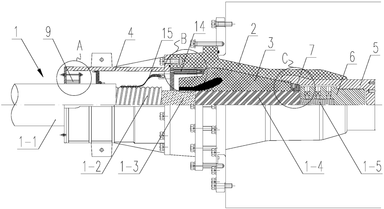
[0004] The technical problem to be solved by the present invention is: in order to solve the thermal expansion and contraction of the cable terminal due to heating and cooling during the power-on and power-off process in the prior art, and the influence of the stress of the cable itself when the cable expands and contracts with heat, As a result, the relative displacement between the cable insulation layer and the cable core is easy to occur. Once the relative displacement between the cable insulation layer and the cable core occurs, it will greatly affect the electric field distribution inside the terminal, which will lead to partial discharge and even breakdown of the terminal. Phenomenon, with high potential safety hazards, now provides a high-voltage dry-type insulated power cable equipment terminal, which can be applied to 245KV transformers or GIS (gas insulated switchgear)

Method used


Image

  • High-voltage dry type insulated power cable equipment terminal
  • High-voltage dry type insulated power cable equipment terminal
  • High-voltage dry type insulated power cable equipment terminal

Examples


Embodiment 1

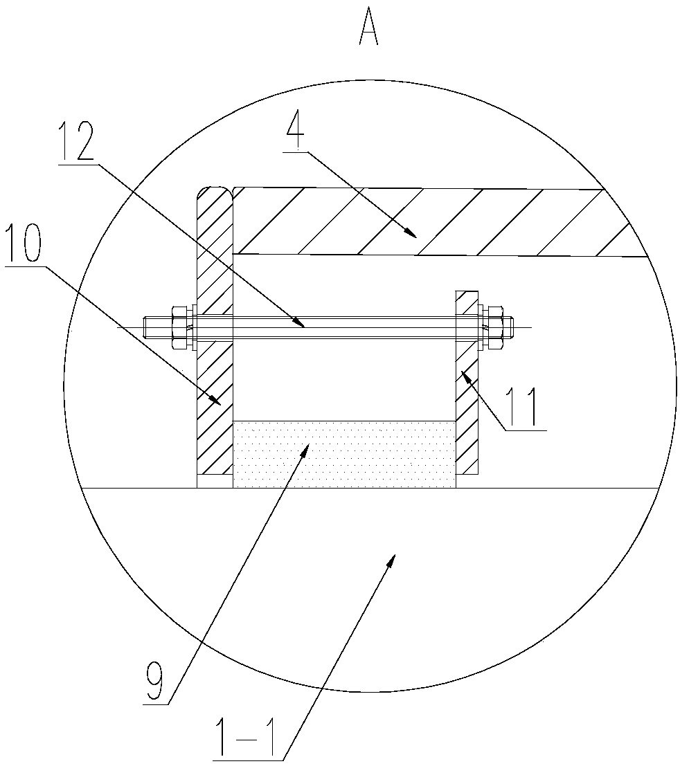
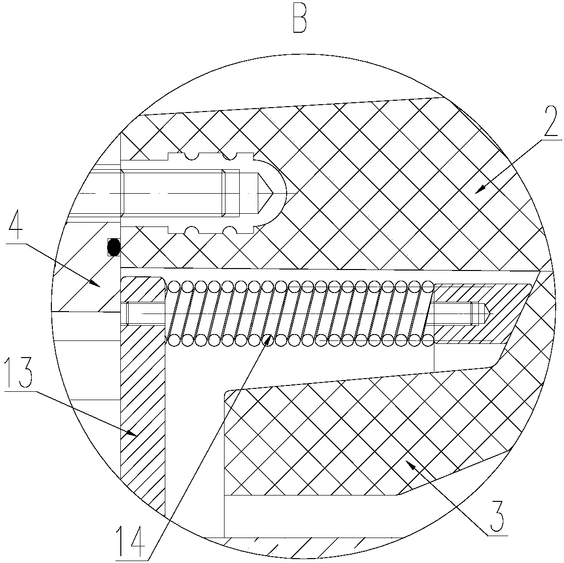
[0025] Such as Figure 1-4 As shown, a high-voltage dry-type insulated power cable equipment terminal includes an insulating bushing 2, a stress cone 3 arranged in the insulating bushing 2, a tail pipe 4 arranged at the inlet end of the insulating bushing 2, and a tail pipe 4 arranged in the insulating bushing 2. The connecting fitting 5 at the outlet end and the connecting contact 6 arranged in the connecting fitting 5, the tail pipe 4 and the connecting fitting 5 are respectively fixed at both ends of the insulating sleeve 2;

[0026] The cable 1 passes through the tail pipe 4 and the insulating sleeve 2, a section of the exposed core section 1-5 is exposed at the front end of the cable 1, and an exposed section 1 of the insulating layer is exposed on the part of the cable 1 adjacent to the exposed section 1-5 of the core -4;

[0027] Such as Figure 4 As shown, the core exposed section 1-5 is fixed in the connecting contact 6, the stress cone 3 is sleeved on the insulatin...


PUM


Abstract

The invention belongs to the cable terminal technical field and relates to a high-voltage dry type insulated power cable equipment terminal. The terminal comprises an insulating bushing, a stress conedisposed in the insulating bushing, a tail pipe disposed at the inlet end of the insulating bushing, a connecting fitting disposed at the outlet end of the insulating bushing, and a connecting contact disposed in the connecting fitting; a positioning ring is disposed in the outlet end of the insulating bushing; and the positioning ring is fixed on the exposed section of an insulating layer. According to the high-voltage dry type insulated power cable equipment terminal of the invention, the positioning ring is fixed onto the exposed section of the insulating layer of a cable, so that the insulating layer of the cable can be effectively prevented from retracting, and a positioning and shape keeping effect is realized for the stress cone, discharge or even breakdown inside the terminal caused by the retraction of the insulating layer of the cable can be avoided; the safety performance of the terminal is high; the cable can be prevented from falling relative to the terminal; and no flames and no high temperature appear during the installation process of the terminal. The high-voltage dry type insulated power cable equipment terminal is safe, reliable, and environmentally friendly, and especially suitable for high-risk places such as coal mines, chemical enterprises and high-demand substations.

Description

technical field [0001] The invention relates to the technical field of cable terminals, in particular to a high-voltage dry-type insulated power cable equipment terminal. Background technique [0002] With the expansion of urban power grid construction, the demand for cable terminals used to support GIS or transformer equipment is also increasing simultaneously. At present, the existing cable terminals mainly include insulating sleeves (epoxy master molds) and insulating sleeves located in the insulating sleeves. Stress cone and fittings, the cable passes through the stress cone and is electrically connected with the connecting contact in the fitting with the wire core at the end, the stress cone is covered on the insulating layer of the cable, and the stress cone is positioned by the spring compression device; [0003] With the use, it is found that this type of cable terminal obviously has the following defects: the cable will heat and cool during the process of power-on a...

Claims


Application Information

Patent Timeline
Patent Type & Authority Applications(China)
IPC IPC(8): H02G15/06H02G15/064
CPCH02G15/06H02G15/064
Inventor 朱志存金良贊王山山
Owner 信承瑞(常州)电力技术有限公司
Learn More