
Drilling machine with mold clamping function

A drilling machine and mold technology, which is applied in boring/drilling, drilling/drilling equipment, clamping, etc., can solve the problems of easy deviation of workpiece, reduced drilling quality, and deviation of drill bit from the drilling direction, etc. To achieve the effect of compact structure, good use effect and improved stability

Inactive Publication Date: 2018-09-11
刘宏纲
View PDF0 Cites 9 Cited by
  • Summary
  • Abstract
  • Description
  • Claims
  • Application Information

AI Technical Summary

Problems solved by technology

The traditional drilling machine only drives it through the driving device to make the drill bit rotate. When the drilling force is too large, because there is no auxiliary mechanism to guide it at the joint of the drill bit, it is often easy to cause the drill bit to rotate due to excessive drilling force. The drill bit is too large to deviate from the drilling direction, thereby reducing the drilling quality, and when drilling, generally the workpiece waiting for the mold to be drilled is placed directly under the drill bit, and there is no limit and clamp for fixing it. It is tight, so that some workpieces are easy to deviate from the position when drilling, and the use effect is not good

Method used


Image

  • Drilling machine with mold clamping function
  • Drilling machine with mold clamping function

Examples


Embodiment Construction

[0015] The following will clearly and completely describe the technical solutions in the embodiments of the present invention with reference to the accompanying drawings in the embodiments of the present invention. Obviously, the described embodiments are only some, not all, embodiments of the present invention.

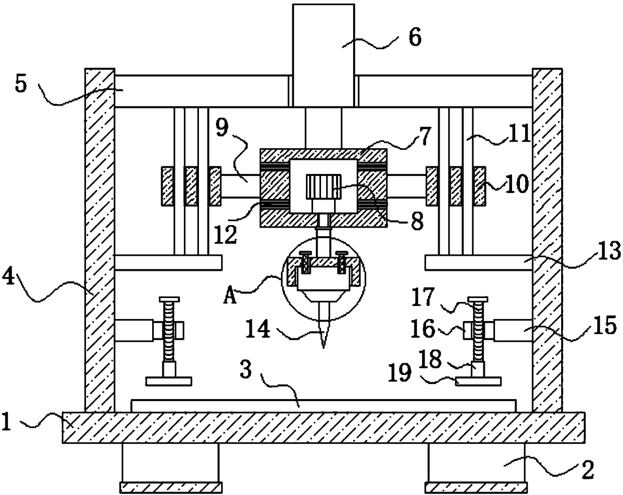
[0016] refer to Figure 1-2 , a mold clamping drilling machine, including an operation table 1, the four corners of the lower end of the operation table 1 are fixedly connected with a support seat 2, and the upper end of the operation table 1 is fixedly connected with a mold placement table 3, and the mold workpiece is placed on the mold placement table 3, both sides of the upper end of the console 1 are fixedly connected with a support plate 4, a fixed plate 5 is fixedly connected between the opposite side walls of the two support plates 4 close to the upper end, and a hydraulic cylinder 6 is fixedly connected with the upper end of the fixed plate 5, The telescopic ...


PUM


Abstract

The invention discloses a drilling machine with a mold clamping function. The drilling machine comprises an operation table, supporting seats are fixedly connected to the four corners of the lower endof the operation table correspondingly, a mold placing table is fixedly connected to the upper end of the operation table, and supporting plates are fixedly connected to the two sides of the upper end of the operation table correspondingly; a fixing plate is fixedly connected between the opposite side walls, close to the upper ends, of the two supporting plates, and a hydraulic oil cylinder is fixedly connected to the upper end of the fixing plate; and the telescopic end of the hydraulic oil cylinder penetrates through the fixing plate and is fixedly connected with a placing plate, a placinggroove is formed in the placing plate, and a rotating motor is fixedly connected in the placing groove. According to the drilling machine with the mold clamping function, the structure is compact, andguide mechanisms are arranged at the connecting positions of a drilling mechanism, so that a drill bit is prevented from deviating from the drilling direction to a certain extent due to the fact thatthe drilling force of the drill bit is too large; and moreover, limiting mechanisms for clamping a mold workpiece are arranged, so that the stability of the mold workpiece is improved, and the use effect is very good.

Description

technical field [0001] The invention relates to the technical field of machinery, in particular to a mold clamping drilling machine. Background technique [0002] Drilling machine is a general term for machinery and equipment that uses a tool that is harder and sharper than the target to leave a cylindrical hole or hole on the target by means of rotary cutting or rotary extrusion. With the development of the times, the drilling technology of automatic drilling machines is also constantly improving, and more and more construction sites are also using drilling machines, especially drilling machines for drilling molds and other workpieces. The traditional drilling machine only drives it through the driving device to make the drill bit rotate. When the drilling force is too large, because there is no auxiliary mechanism to guide it at the joint of the drill bit, it is often easy to cause the drill bit to rotate due to excessive drilling force. The drill bit is too large to devi...

Claims


Application Information

Patent Timeline
IPC IPC(8): B23B41/00B23B49/00B23B47/22B23Q3/06
CPCB23B41/00B23B49/00B23Q3/062B23Q5/34
Inventor 刘宏纲
Owner 刘宏纲
Learn More