
Combined connector

A connecting head and combined technology, which is applied in the direction of socket/socket connection, pipe/pipe joint/pipe fitting, passing element, etc., can solve the problems of high equipment investment cost, easy breakage, long construction period, etc., and save special equipment The effect of low investment cost, not easy to break, and reliable performance

Inactive Publication Date: 2018-09-07
广东思豪流体技术有限公司
View PDF6 Cites 1 Cited by
  • Summary
  • Abstract
  • Description
  • Claims
  • Application Information

AI Technical Summary

Problems solved by technology

[0002] The traditional method for the installation of fluid delivery pipelines is to weld two metal pipelines. However, most of the existing fluid pipelines, especially compressed air pipelines, are erected at a certain height, so a higher construction frame is generally required. After lifting the pipes to be welded to the construction frame, experienced welders will carry out the welding. This method is not only difficult to construct, but also has a long construction period, and there are also potential safety hazards during welding. Now the technology is used in the ring-shaped installation groove. The sealing device seals the joints of the two conveying pipes that need to be connected. In order to prevent the pipes from retreating axially under high pressure and detaching from the connecting device body, a limit groove set on the inner wall of the metal shell is used. The protruding rings on the pipeline are snapped together to locate the
The connection device of this structure has the following problems. First, the pipeline sold in the pipeline processing factory does not exist, which requires special equipment to be produced on the installation site. On the one hand, the investment cost of special equipment is high. On the other hand, highly experienced technicians are needed to operate a qualified protruding ring. If there is a slight carelessness, the protruding ring produced does not meet the requirements. The pipe head with unqualified convex ring that is sawed off from the conveying pipeline is also a kind of waste to the conveying pipeline; After the two half-shells of the metal shell are stuck on the pipeline, the screws can be locked, which makes it difficult to install in a relatively narrow space. At the same time, the existing connectors are made of high-carbon steel or aluminum alloy. Its toughness is poor, and it is easy to break in an environment with more vibrations

Method used


Image

  • Combined connector
  • Combined connector
  • Combined connector

Examples


Embodiment Construction

[0014] The specific implementation manners of the present invention will be described in further detail below in conjunction with the accompanying drawings.

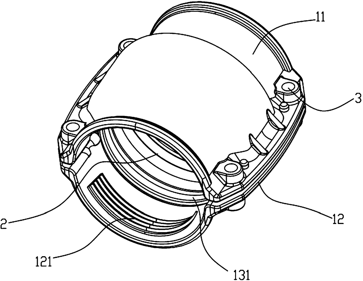
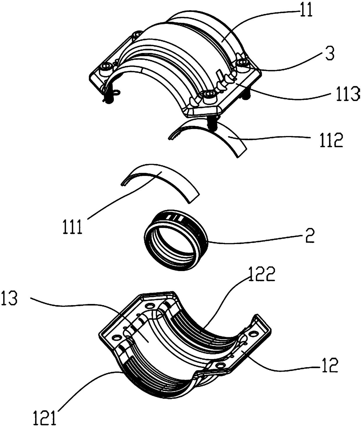
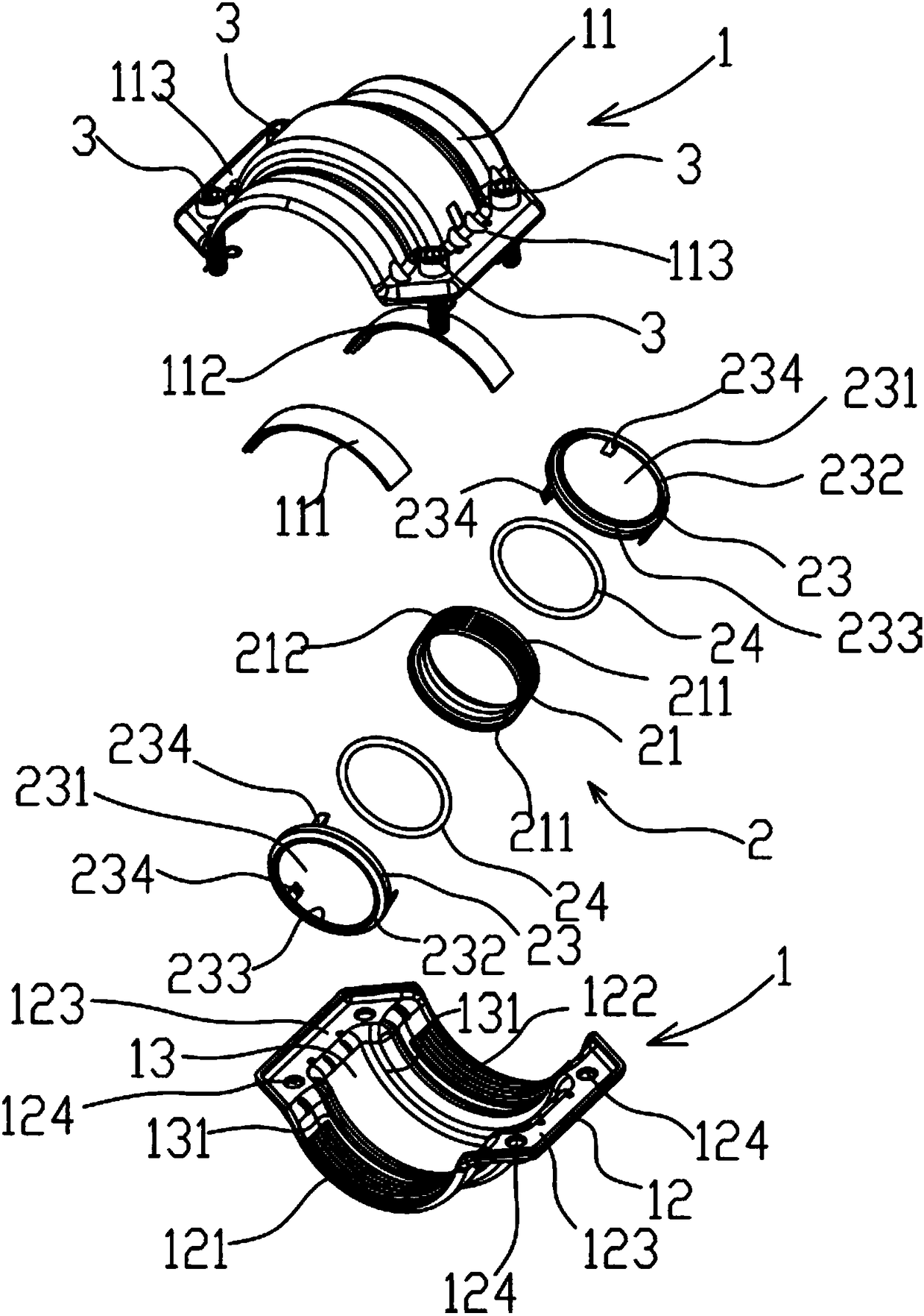
[0015] See attached Figure 1-3 , the present invention includes an outer casing 1 and a sealing device 2, the outer casing 1 is composed of a first semi-annular body 11 and a second semi-annular body 12, and the first semi-annular body 11 and the second semi-annular body 12 are connected by a fastener 3 , the inner cavity of the outer casing 1 is provided with an annular mounting groove 13, and the sealing device 2 is arranged in the annular mounting groove 13, and is characterized in that: on the inner wall of the first semi-annular body 11, it is installed by the annular The outer two ends of the groove 13 are respectively provided with a first arc-shaped sawtooth plate 111 and a second arc-shaped sawtooth plate 112. The third arc-shaped sawtooth plate 121 and the second arc-shaped sawtooth plate 122, the outer shell...


PUM


Abstract

The invention discloses a combined connector comprising an outer shell body and a sealing device. The outer shell body is composed of a first semi-ring body and a second semi-ring body, the first semi-ring body and the second semi-ring body are connected through fasteners. An inner cavity of the outer shell body is internally provided with an annular installation slot, and the sealing device is arranged in the annular installation slot. The combined connector is characterized in that the two ends, close to the outer side of the annular installation slot, of the inner wall of the first semi-ring body are provided with a first arc saw tooth plate and a second arc saw tooth plate correspondingly, the two ends, close to the outer side of the annular installation slot, of the inner wall of thesecond semi-ring body are provided with a third arc saw tooth plate and a fourth arc saw tooth plate correspondingly, and the outer shell body is made of a carbon fiber composite material.

Description

technical field [0001] The present invention relates to a joint, in particular to a combined joint. Background technique [0002] The traditional method for the installation of fluid delivery pipelines is to weld two metal pipelines. However, most of the existing fluid pipelines, especially compressed air pipelines, are erected at a certain height, so a higher construction frame is generally required. After lifting the pipes to be welded to the construction frame, experienced welders will carry out the welding. This method is not only difficult to construct, but also has a long construction period, and there are also potential safety hazards during welding. Now the technology is used in the ring-shaped installation groove. The sealing device seals the joints of the two conveying pipes that need to be connected. In order to prevent the pipes from retreating axially under high pressure and detaching from the connecting device body, a limit groove set on the inner wall of the m...

Claims


Application Information

Patent Timeline
Patent Type & Authority Applications(China)
IPC IPC(8): F16L21/06
CPCF16L21/06
Inventor 周富强
Owner 广东思豪流体技术有限公司
Learn More