
Heat treatment method of steel rail flash welding head

A heat treatment method and welding head technology, used in heat treatment furnaces, heat treatment equipment, furnaces, etc., can solve the problems of complicated operation and implementation process and high cost, and achieve the effect of improving wear and ensuring safety.

Active Publication Date: 2018-09-07
PANZHIHUA IRON & STEEL RES INST OF PANGANG GROUP
View PDF2 Cites 34 Cited by
  • Summary
  • Abstract
  • Description
  • Claims
  • Application Information

AI Technical Summary

Problems solved by technology

The dissimilar rail welded joints obtained by this method can meet the test requirements for fatigue, tensile, impact and static bending tests in the current domestic railway industry standard TB / T1632.2-2014 "Rail Welding Part 2: Flash Welding"; but The above-mentioned invention involves post-weld normalizing heat treatment of rails, which requires the use of post-weld heat treatment equipment to locally heat the welded joints of the rails. The operation and implementation process is complicated and the cost is relatively high.

Method used


Image

  • Heat treatment method of steel rail flash welding head
  • Heat treatment method of steel rail flash welding head
  • Heat treatment method of steel rail flash welding head

Examples

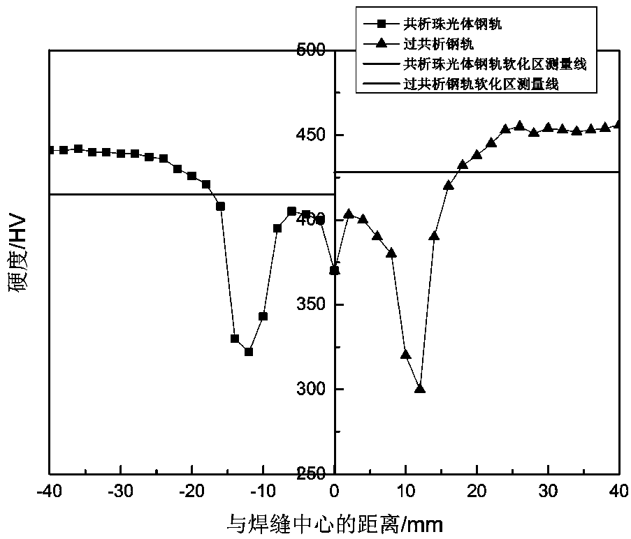

Embodiment 1

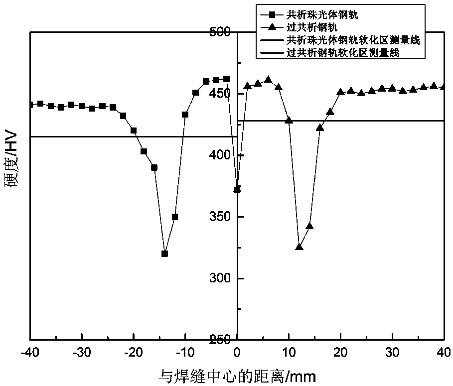
[0036] After the rails with a specification of 60kg / m have completed upsetting and push-out during the mobile flash welding process, the welded joints are subjected to post-weld heat treatment. Firstly, the rail joint with residual temperature of 1100 °C obtained by welding is cooled in the first stage at the first cooling rate of 7.0 °C / s to reduce the surface temperature of the rail head of the rail joint to 660 °C, and then the rail joint is cooled at 2.0 °C The second cooling rate of / s is used for the second-stage cooling to reduce the surface temperature of the rail head of the rail joint to 400°C, and finally the rail joint is subjected to the third-stage cooling at a third cooling rate of 0.4°C / s to reduce the temperature of the rail joint The temperature of the surface layer of the rail head is lowered to the room temperature of 25° C., thereby obtaining the welded joint of the rail with post-weld heat treatment of the present invention.

[0037] In the post-weld heat...

Embodiment 2

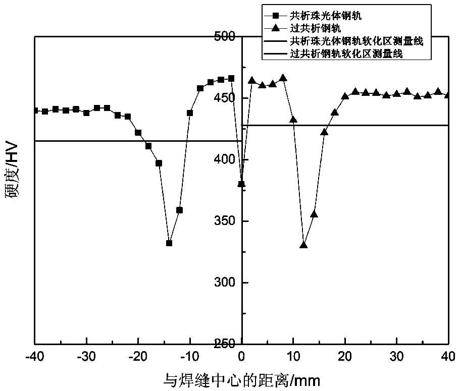
[0045] After the rail with a specification of 68kg / m has completed the upsetting and push-out during the mobile flash welding process, the welded joint is subjected to post-weld heat treatment. Firstly, the rail joint with residual temperature of 1000 °C after welding is cooled in the first stage at the first cooling rate of 6.5 °C / s to reduce the surface temperature of the rail head of the rail joint to 680 °C, and then the rail joint is cooled at 2.2 °C The second cooling rate of / s is used for the second-stage cooling to reduce the surface temperature of the rail head of the rail joint to 380°C, and finally the rail joint is subjected to the third-stage cooling at a third cooling rate of 0.10°C / s to reduce the temperature of the rail joint The temperature of the surface layer of the rail head is lowered to room temperature of 25° C., thereby obtaining the post-weld heat-treated rail welded joint of dissimilar materials of the present invention.

[0046] In the post-weld hea...


PUM

PropertyMeasurementUnit
Softening zone widthaaaaaaaaaa

Abstract

The invention discloses a heat treatment method of a steel rail flash welding head, and belongs to the technical field of steel rail welding. The invention aims to solve the technical problems of saddle type abrasion and early-stage fatigue fracture of a steel rail welding head due to the fact that the hardness of a welding area is lower or the welding head microstructure is abnormal in the line service process of the steel rail, the heat treatment method of the steel rail flash welding head is provided, the steel rail welding head is sequentially subjected to a first cooling stage, a second cooling stage and a third cooling stage, the cooling speed and the temperature of each stage are controlled, so that abnormal tissues such as martensite, bainite and the like are not exist in the metallographic structure of the steel rail welding head. The heat treatment method of steel rail flash welding head has the beneficial effects that saddle type abrasion and early-stage fatigue fracture ofthe steel rail welding head due to the fact that the hardness of the welding area is lower or the welding head microstructure is abnormal in the line service process of the steel rail are improved, and the safety of railway operation is guaranteed.

Description

technical field [0001] The invention belongs to the technical field of rail welding, and in particular relates to a heat treatment method for rail flash welding joints. Background technique [0002] At present, eutectoid pearlitic steel rails are mostly used in heavy-duty railway lines at home and abroad. The carbon content of such steel rails is usually in the range of 0.72-0.82 wt%. Moderate features. With the rapid development of railways, heavy-duty and heavy-duty lines put forward higher requirements for the service performance of rails, and the comprehensive mechanical properties and welding properties of traditional pearlitic rails have almost reached their limits. In this case, hypereutectoid steel rails with higher strength levels and comprehensive properties such as good wear resistance and contact fatigue have emerged as the times require. The carbon content of such steel rails is usually in the range of 0.90-1.10 wt%. The structure is pearlite + a small amount ...

Claims


Application Information

Patent Timeline
IPC IPC(8): C21D9/50C21D9/04
CPCC21D9/04C21D9/505
Inventor 白威李大东王若愚邓健
Owner PANZHIHUA IRON & STEEL RES INST OF PANGANG GROUP
Learn More