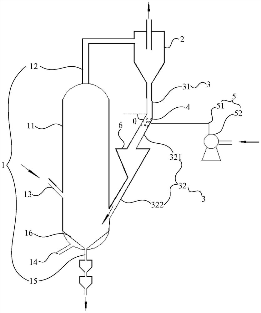
A coal gasification device
A technology of coal gasification and fluidized bed gasification furnace, which is applied to the gasification of granular/powdered fuels, the manufacture of combustible gas, and the petroleum industry. It can solve the problems of short residence time, wear of mechanical valves, and failure of fly ash to return to gasification Furnace and other problems, to achieve the effect of high conversion rate and prolong the running time
- Summary
- Abstract
- Description
- Claims
- Application Information
AI Technical Summary
Problems solved by technology
Method used
Image

Examples
Embodiment Construction
[0028] The following will clearly and completely describe the technical solutions in the embodiments of the present invention with reference to the accompanying drawings in the embodiments of the present invention. Obviously, the described embodiments are only some, not all, embodiments of the present invention. Based on the embodiments of the present invention, all other embodiments obtained by persons of ordinary skill in the art without making creative efforts belong to the protection scope of the present invention.
[0029] It should be noted that, for the convenience of description, the azimuth relationship between the various structures in the coal gasification device described in the present invention refers to the azimuth relationship between the internal structures of the coal gasification device when it is in use, and It is not to indicate or imply that referenced structures must have a particular orientation, be constructed in a particular orientation, or operate in ...
PUM
| Property | Measurement | Unit |
|---|---|---|
| angle | aaaaa | aaaaa |
Abstract
Description
Claims
Application Information
 - R&D
- Intellectual Property
- Life Sciences
- Materials
- Tech Scout
- Unparalleled Data Quality
- Higher Quality Content
- 60% Fewer Hallucinations
Browse by: Latest US Patents, China's latest patents, Technical Efficacy Thesaurus, Application Domain, Technology Topic, Popular Technical Reports.
© 2025 PatSnap. All rights reserved.Legal|Privacy policy|Modern Slavery Act Transparency Statement|Sitemap|About US| Contact US: help@patsnap.com