
Seal weld surfacing maintenance device

A technology for sealing welds and welding wires, applied in welding equipment, arc welding equipment, manufacturing tools, etc., can solve the problems of complex maintenance equipment structure, high dependence on foreign imports for sealing weld maintenance, long maintenance cycle, etc., to achieve surfacing maintenance The effect of shortening time and pre-service welding time, reducing maintenance and pre-service welding operation costs, and shortening maintenance cycle

Active Publication Date: 2018-09-07
STATE NUCLEAR POWER PLANT SERVICE
View PDF10 Cites 11 Cited by
  • Summary
  • Abstract
  • Description
  • Claims
  • Application Information

AI Technical Summary

Problems solved by technology

The maintenance surfacing welding technology in the United States is the overall surfacing welding on the basis of retaining the original CRDM components and their sealed welds. Compared with the French CRDM overall replacement technology, it has good technical reliability, relatively short maintenance cycle, and relatively good economy , but the structure of the maintenance equipment in this technology is complex, the size is large, the process control is cumbersome, and the maintenance cost is extremely high
At present, when such leakage failures of sealing welds occur in China, the maintenance of sealing welds is highly dependent on foreign imports. Not only is the cost quite expensive, but also the maintenance cycle is long, which seriously affects the operating efficiency of nuclear power plants.

Method used


Image

  • Seal weld surfacing maintenance device
  • Seal weld surfacing maintenance device
  • Seal weld surfacing maintenance device

Examples


Embodiment Construction

[0104] The implementation of the present invention will be illustrated by specific specific examples below, and those skilled in the art can easily understand other advantages and effects of the present invention from the contents disclosed in this specification.

[0105]It should be noted that the structures, proportions, sizes, etc. drawn in the drawings of this specification are only used to match the content disclosed in the specification, for those who are familiar with this technology to understand and read, and are not used to limit the conditions for the implementation of the present invention. Therefore, there is no technical substantive meaning, and any modification of structure, change of proportional relationship or adjustment of size shall still fall within the scope of the disclosure of the present invention without affecting the functions and objectives of the present invention. within the scope of technical content. At the same time, terms such as "upper", "low...


PUM


Abstract

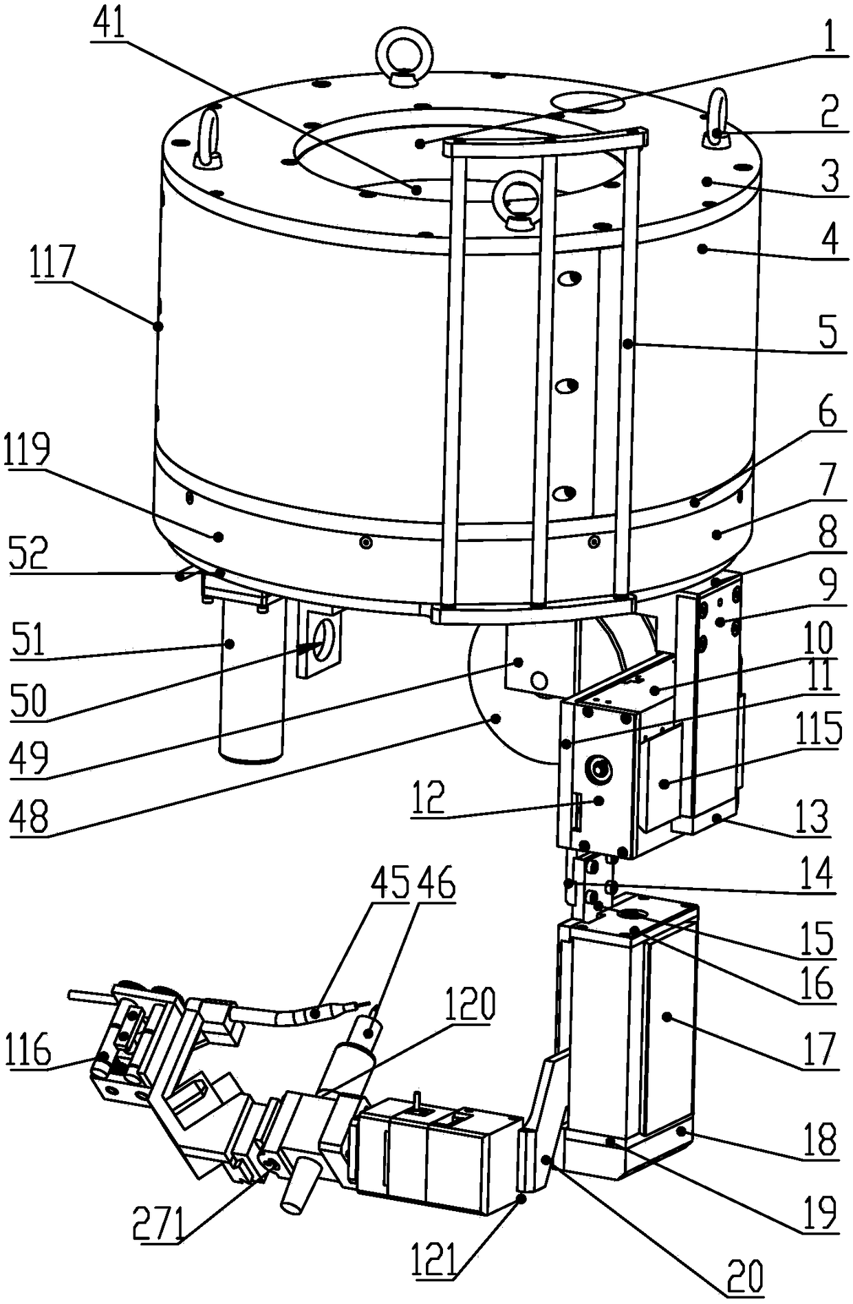
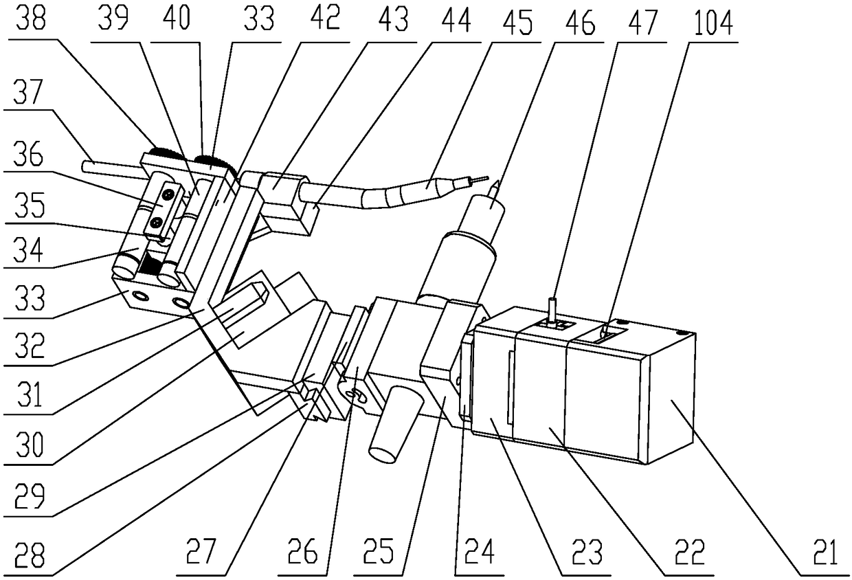
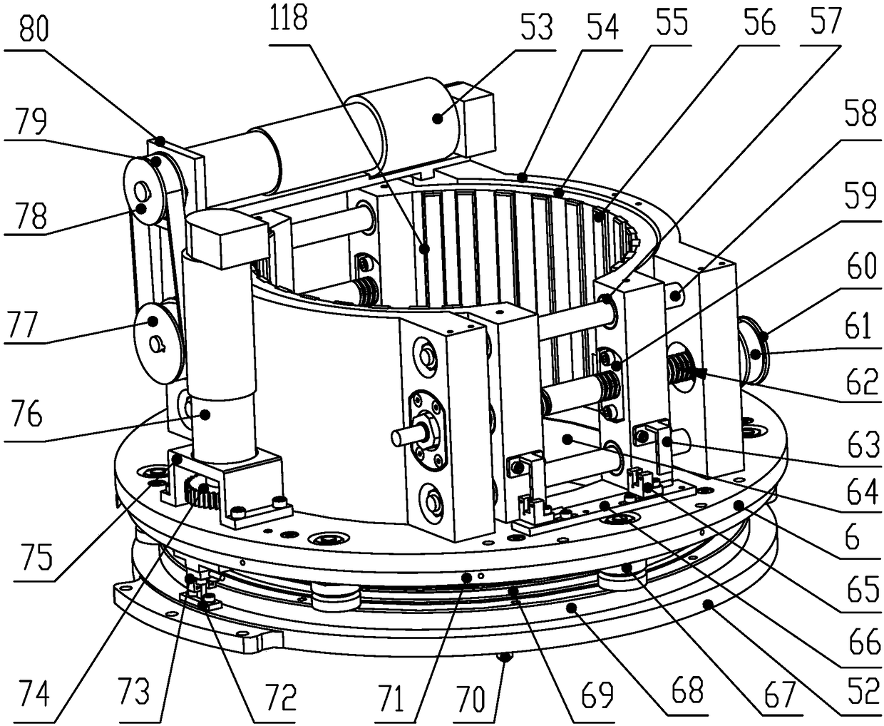
The invention provides a seal weld surfacing maintenance device. The seal weld surfacing maintenance device comprises a mounting base with a containing inner cavity, a clamping mechanism, a rotating mechanism and a welding module. A mounting through groove which is vertically through and is used for allowing a seal weld carrier to penetrate into is formed in the mounting base. The mounting base isprovided with a rotating mechanism fixing plate located at the lower end of the containing inner cavity. The clamping mechanism is arranged in the containing inner cavity of the mounting base and provided with two symmetrically-arranged clamping stirrups, and the two clamping stirrups can oppositely move in the radial direction of the seal weld carrier so as to fix the mounting base to the periphery of the seal weld carrier. The rotating mechanism is installed on the lower end face of the rotating mechanism fixing plate and provided with a welding motion fixing plate capable of rotating in the circumferential direction of the seal weld carrier. The welding module is installed on the welding motion fixing plate and provided with a welding assembly and a wire feeding nozzle assembly. By means of the seal weld surfacing maintenance device, the automatic surfacing operation can be achieved, operation is simple, the mounting time is short, the surfacing maintenance time is shortened, and the seal weld maintenance operation cost is greatly reduced.

Description

technical field [0001] The invention relates to the fields of welding, surfacing and maintenance of sealing welds, in particular to a sealing welding surfacing maintenance device for a control rod drive mechanism (CRDM) of a nuclear power plant. Background technique [0002] The control rod drive mechanism (hereinafter referred to as CRDM) is the servo mechanism of the reactor control and safety protection system. Its function is to drive the control rod assembly to move up and down in the core according to the instructions of the reactor control and protection system, and to keep the control rod assembly in the reactor core. The safety and reliability of reactor start-up, power adjustment, power maintenance, safety shutdown and emergency shutdown are completed by command height or power failure and rod drop, which directly affect the safety and operation of the reactor. There are multiple control rod drive mechanisms distributed on the top cover of the reactor pressure vess...

Claims


Application Information

Patent Timeline
Patent Type & Authority Applications(China)
IPC IPC(8): B23K9/04B23K9/133
CPCB23K9/048B23K9/133Y02E30/30
Inventor 文忠俞照辉闫国华李玮叶琛徐进津
Owner STATE NUCLEAR POWER PLANT SERVICE
Learn More