Forging and pressing device and method special for coal mine hydraulic support cylinder barrel

A technology of coal mine hydraulic and forging equipment, applied in forging/pressing/hammering machinery, forging presses, forging presses, etc., can solve the problems of heavy weight, weak firmness, inconvenient heating, etc., and achieve high production efficiency and low labor intensity , the effect of simple structure

Pending Publication Date: 2018-09-07
邓州市良机锻压设备制造有限公司
View PDF1 Cites 1 Cited by
  • Summary
  • Abstract
  • Description
  • Claims
  • Application Information

AI Technical Summary

Problems solved by technology

[0002] At present, the hydraulic support cylinder used in coal mines has an integrated structure, which is prepared by surfacing welding. The material of the cylinder and the surfacing welding part prepared by the above method is inconsistent, which is inconvenient for heat treatment. Low defect, easily damaged during use, directly affects the safety of coal mines; therefore people try to use forging to prepare the cylinder to ensure its quality, but there are the following problems in the actual operation process: 1. Inconvenient heating ;The cylinder is large in size, weight and height. During the heating process, only one end of the cylinder needs to be heated. The traditional lifting equipment cannot complete the above work. For example, the cylinder is directly placed into the heating furnace by using the lifting equipment When heating, because it cannot be fixed, it will not only affect the service life of the hoisting equipment and the heating furnace, but also cause a major safety accident in severe cases; The distance between them is too short, which directly causes the parts to be forged to be unable to be placed in the die; due to the above problems, the method of forging the cylinder has not been realized

Method used


Image

  • Forging and pressing device and method special for coal mine hydraulic support cylinder barrel
  • Forging and pressing device and method special for coal mine hydraulic support cylinder barrel
  • Forging and pressing device and method special for coal mine hydraulic support cylinder barrel

Examples


Embodiment 1

[0044] A forging method of special forging equipment for coal mine hydraulic support cylinder, comprising the following steps:

[0045] Step 1: Prepare materials: cut seamless steel pipes with a length of 500mm, a diameter of Φ350mm, and a wall thickness of 30mm. The material of the seamless steel pipe is: 30CrMnSi;

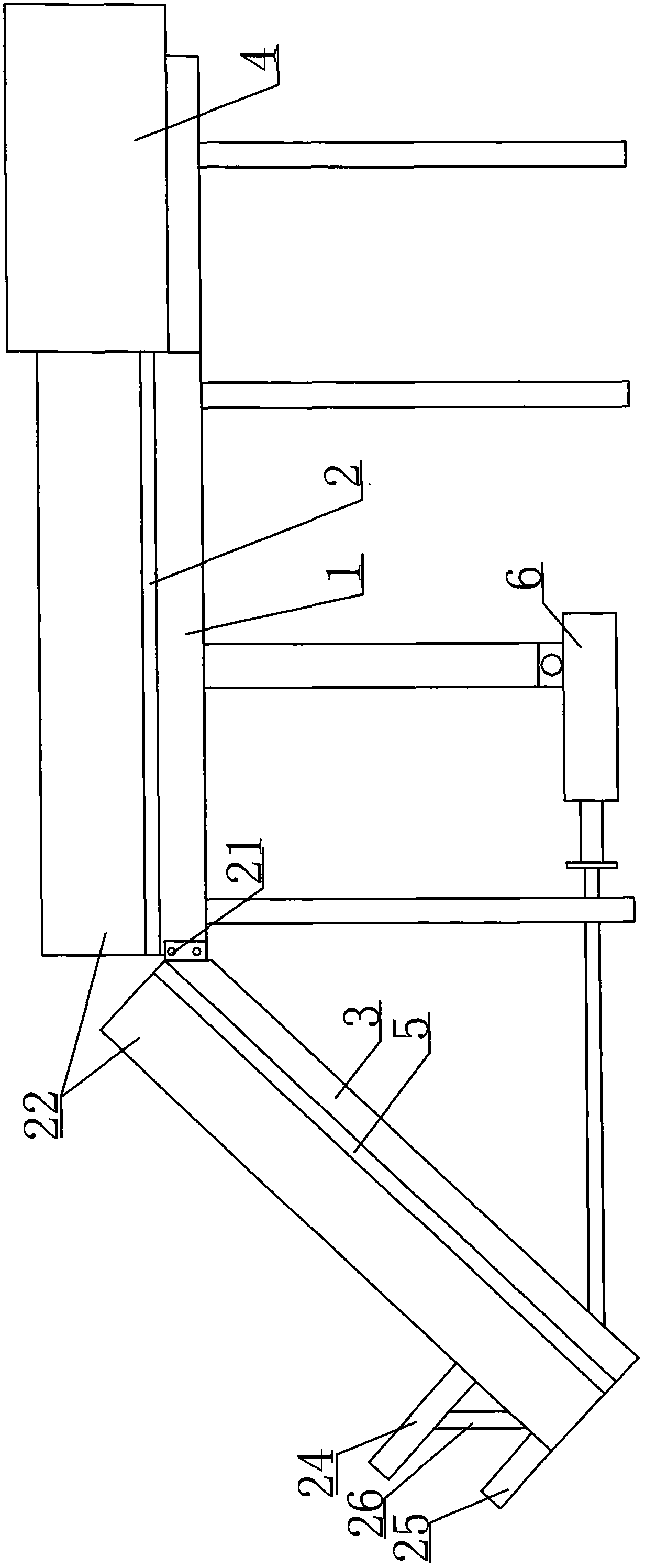
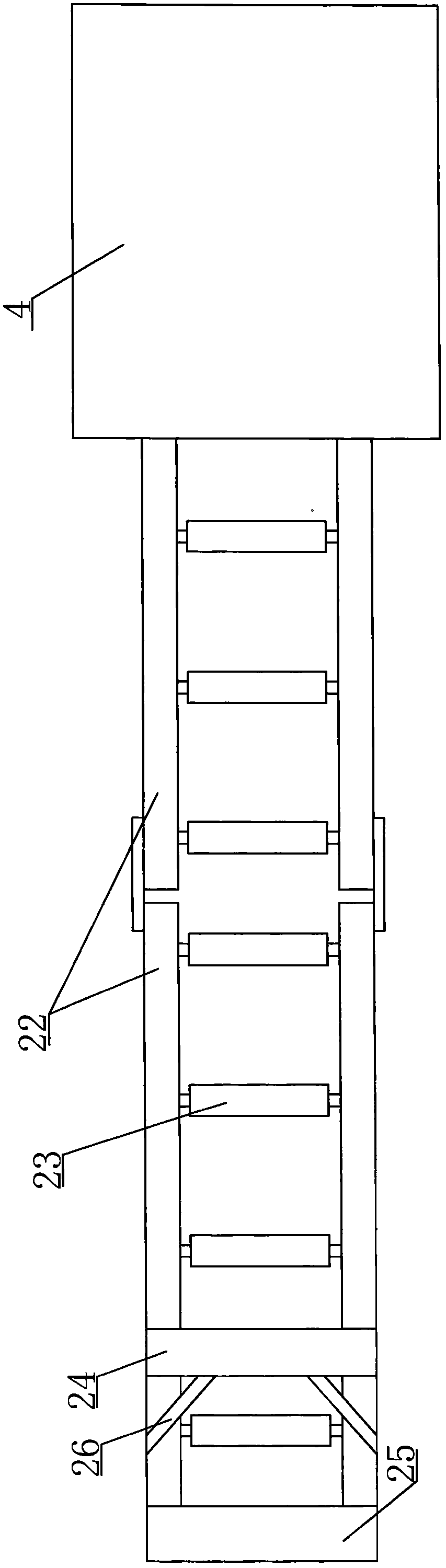
[0046] Step 2: Heating: horizontally place the seamless steel pipe described in step 1 on the fixed track 2 by hoisting equipment, and the end of the seamless steel pipe to be heated is close to the side of the intermediate frequency heating furnace 4;

[0047] Step 3: Manually push the end of the seamless steel pipe to be heated into the intermediate frequency heating furnace 4 for heating to 1000-1100°C;

[0048] Step 4: Manually push and pull the heated seamless steel pipe to the top of the fixed support 1, start the hydraulic cylinder 6, and recover the piston rod end of the hydraulic cylinder 6, and the movable support 3 tilts slowly, and the heated seamless...

Embodiment 2

[0055] A forging method of special forging equipment for coal mine hydraulic support cylinder, comprising the following steps:

[0056] Step 1: Prepare materials: cut seamless steel pipes with a length of 2500mm, a diameter of Φ475mm, and a wall thickness of 65mm. The material of the seamless steel pipe is: 35CrMnSi;

[0057] Step 2: Heating: horizontally place the seamless steel pipe described in step 1 on the fixed track 2 by hoisting equipment, and the end of the seamless steel pipe to be heated is close to the side of the intermediate frequency heating furnace 4;

[0058] Step 3: Manually push the end of the seamless steel pipe to be heated into the intermediate frequency heating furnace 4 for heating to 1000-1100°C;

[0059] Step 4: Manually push and pull the heated seamless steel pipe to the top of the fixed support 1, start the hydraulic cylinder 6, and recover the piston rod end of the hydraulic cylinder 6, and the movable support 3 tilts slowly, and the heated seamles...

Embodiment 3

[0067] A forging method of special forging equipment for coal mine hydraulic support cylinder, comprising the following steps:

[0068] Step 1: Prepare materials: cut seamless steel pipes with a length of 1500mm, a diameter of Φ400mm, and a wall thickness of 45mm. The material of the seamless steel pipe is: 30CrMnSi;

[0069] Step 2: Heating: horizontally place the seamless steel pipe described in step 1 on the fixed track 2 by hoisting equipment, and the end of the seamless steel pipe to be heated is close to the side of the intermediate frequency heating furnace 4;

[0070] Step 3: Manually push the end of the seamless steel pipe to be heated into the intermediate frequency heating furnace 4 for heating to 1000-1100°C;

[0071] Step 4: Manually push and pull the heated seamless steel pipe to the top of the fixed support 1, start the hydraulic cylinder 6, and recover the piston rod end of the hydraulic cylinder 6, and the movable support 3 tilts slowly, and the heated seamles...


PUM

PropertyMeasurementUnit
lengthaaaaaaaaaa
diameteraaaaaaaaaa
lengthaaaaaaaaaa

Abstract

The invention belongs to a forging and pressing device and method special for a coal mine hydraulic support cylinder barrel. The forging and pressing device comprises a heating support and a forging and pressing die. The heating support comprises a fixed support, and a fixing rail is arranged at the top of the fixed support. A movable support is arranged at the front end of the fixed support, andan intermediate-frequency heating furnace is arranged at the tail end of the fixed support. The forging and pressing die comprises a movable male die unit arranged at the piston rod end of a large-tonnage hydraulic machine, and a female die unit is arranged on the corresponding position at the bottom of the movable male die unit. The male die unit comprises an upper die fixing plate arranged at the piston rod end of the large-tonnage hydraulic machine, and guide rails are mounted on the two sides of the bottom of the upper die fixing plate. A movable base plate is mounted between the two guiderails, and a male die used for a forging and pressing cylinder barrel is arranged at the bottom of the movable base plate. The forging and pressing device and method have the advantages that the structure is simple, design is reasonable, the production efficiency is high, the labor intensity is low, and the cylinder barrel can be formed in forging and pressing modes in the closed die at a time.

Description

technical field [0001] The invention belongs to the technical field of production of hydraulic support cylinders for coal mines, and in particular relates to special forging equipment and a forging method for coal mine hydraulic support cylinders. Background technique [0002] At present, the hydraulic support cylinder used in coal mines has an integrated structure, which is prepared by surfacing welding. The material of the cylinder and the surfacing welding part prepared by the above method is inconsistent, which is inconvenient for heat treatment. Low defect, easily damaged during use, directly affects the safety of coal mines; therefore people try to use forging to prepare the cylinder to ensure its quality, but there are the following problems in the actual operation process: 1. Inconvenient heating ;The cylinder is large in size, weight and height. During the heating process, only one end of the cylinder needs to be heated. The traditional lifting equipment cannot comp...

Claims


Application Information

Patent Timeline
Patent Type & Authority Applications(China)
IPC IPC(8): B21J9/02B21J1/06B21J13/02B21J13/03B21J5/00
CPCB21J1/06B21J5/00B21J9/02B21J13/02B21J13/03
Inventor 赵普良张召
Owner 邓州市良机锻压设备制造有限公司
Why Eureka
Try Eureka