
Sewage efficient treatment equipment

A kind of treatment equipment and high-efficiency technology, applied in water/sewage treatment equipment, water/sewage treatment, biological water/sewage treatment, etc., can solve the problems of incomplete degradation, reduction of eutrophic oxidation in water body, poor separation effect, etc. Accelerate the speed of sewage treatment, high biological sludge concentration, and obvious effect of nitrification

Inactive Publication Date: 2018-09-04
方高健
View PDF1 Cites 0 Cited by
  • Summary
  • Abstract
  • Description
  • Claims
  • Application Information

AI Technical Summary

Problems solved by technology

At present, the sewage treatment technology has basically taken shape, but the eutrophic oxidation of the water body caused by the excessive discharge of nitrogen and phosphorus is still a major problem in water pollution. The purpose of sewage treatment is not only to remove organic matter, but to remove both organic matter and Nitrogen and phosphorus removal, reducing eutrophic oxidation of water body
Existing sewage treatment devices generally use multiple sedimentation tanks to precipitate and separate denitrifying phosphorus-accumulating bacteria. There are many reactors, many steps, small effective volume of reactors, low efficiency, and inconvenient operation. And the use of ultrasonic catalysis technology has complex structure, low flexibility, high energy consumption, high cost, incomplete degradation, long particle precipitation time, and cannot achieve the purpose of rapid water recycling in the production process. When draining, part of the sludge will be discharged with the water flow , the separation effect is not good

Method used


Image

  • Sewage efficient treatment equipment

Examples


Embodiment Construction

[0013] The following will clearly and completely describe the technical solutions in the embodiments of the present invention with reference to the accompanying drawings in the embodiments of the present invention. Obviously, the described embodiments are only some, not all, embodiments of the present invention. Based on the embodiments of the present invention, all other embodiments obtained by persons of ordinary skill in the art without making creative efforts belong to the protection scope of the present invention.

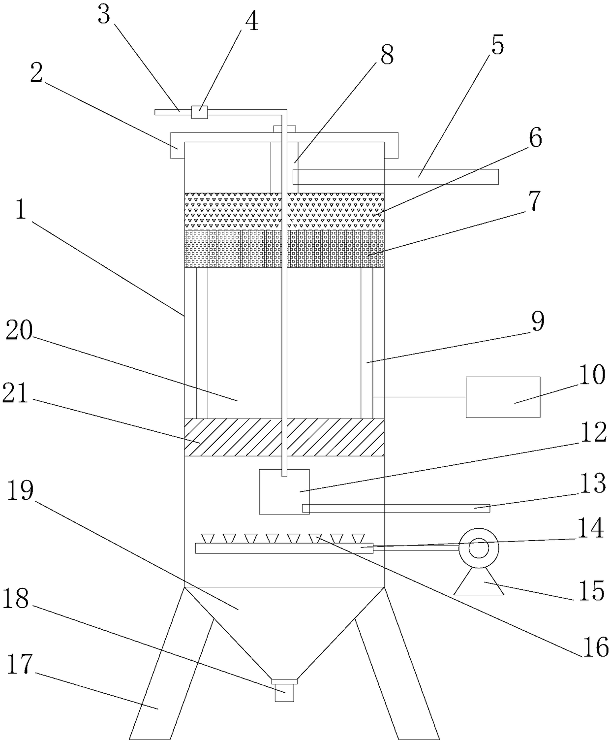
[0014] see figure 1 , in an embodiment of the present invention, a sewage treatment equipment with high efficiency includes a body 1 and an ultrasonic generating device, the top of the body 1 is provided with an upper cover 2, and the upper cover 2 is provided with a water inlet pipe 3, and the inside of the body 1 A buffer box 12 is established, the bottom of the buffer box 12 is provided with an aeration pan 14, and the aeration pan 14 is provided with a plu...


PUM


Abstract

The invention discloses sewage efficient treatment equipment, which comprises a machine body and an ultrasonic generation device, wherein the top end of the machine body is provided with an upper cover; a water inlet pipe is arranged on the upper cover; a buffer box is arranged in the machine body; an aeration disc is arranged at the bottom end of the buffer box; a control valve is arranged on oneend of the water inlet pipe; the other end of the water inlet pipe sequentially passes through the upper cover, a membrane bioreactor, a filtering layer, a filling layer, an ultrasonic reaction layerand a buffer precipitation device to be arranged in the buffer box; an ultrasonic reaction device is arranged in the ultrasonic reaction layer, and comprises ultrasonic plates and two ultrasonic generators; the two ultrasonic plates are respectively and symmetrically arranged in the machine body; the ultrasonic generators are arranged outside the machine body; the two ultrasonic plates are electrically connected with the ultrasonic generators; the upper end of the machine body is provided with a water discharging pipe; one end of the water discharging pipe passes through the machine body to be arranged in the membrane bioreactor. The sewage efficient treatment equipment has the advantages that the structure is simple; organic pollutants can be catalyzed; the sewage is effectively purified; the precipitation is fast.

Description

technical field [0001] The invention relates to a sewage treatment device, in particular to high-efficiency sewage treatment equipment. Background technique [0002] For a long time, industrial sewage has been one of the problems restricting the rapid development of industry, and how to deal with industrial sewage is also a concern of everyone. Therefore, how to scientifically and rationally treat industrial sewage, recycle water resources and fibers, turn waste into treasure, and generate good economic benefits has always been a subject of hard work by experts at home and abroad. At present, the sewage treatment technology has basically taken shape, but the eutrophic oxidation of the water body caused by the excessive discharge of nitrogen and phosphorus is still a major problem in water pollution. The purpose of sewage treatment is not only to remove organic matter, but to remove both organic matter and Nitrogen and phosphorus removal, reducing eutrophic oxidation of wate...

Claims


Application Information

Patent Timeline
IPC IPC(8): C02F9/14C02F101/10C02F101/16C02F101/30
CPCC02F1/001C02F1/28C02F1/36C02F3/02C02F3/1268C02F3/34C02F9/00C02F2001/007C02F2101/105C02F2101/16C02F2101/30C02F2201/007C02F2301/08C02F2303/04
Inventor 方高健
Owner 方高健
Learn More