
Alarm device

一种警报装置、安装面的技术,应用在报警器、火灾报警器、电作用的火灾报警器等方向,能够解决脱模步骤复杂、烟雾误检测、增加制造成本等问题,达到迅速且确实检测的效果

Inactive Publication Date: 2018-08-31
HOCHIKI CORP
View PDF18 Cites 1 Cited by
  • Summary
  • Abstract
  • Description
  • Claims
  • Application Information

AI Technical Summary

Problems solved by technology

[0006] However, in the alarm of Patent Document 1, in order to allow the detection part to be arranged inside the frame, compared with the design in which the detection part is exposed from the frame, since it has the characteristic of reducing the inflow of smoke into the detection part, it is relevant to let the smoke flow into the detection part. There is still room for improvement in the characteristics of the flow into the alarm body or the detection part
[0007] In addition, in the alarm device of Patent Document 1, since the detection part is arranged at a position opposite to the opening, the detection part directly allows interference such as dust, water vapor or ambient light to enter through the opening. , with this intrusion, it is possible to generate false detections of smoke
[0008] In addition, because the overall shape of the alarm containing the vertical grid and the horizontal grid becomes more complicated, when the mold is used to manufacture the alarm, it will be used to form the shape of the alarm (especially if the vertical grid and the horizontal grid are provided). Around the opening of the gate) the demoulding step becomes more complicated, which may also increase the manufacturing cost

Method used


Image

  • Alarm device
  • Alarm device
  • Alarm device

Examples


Embodiment Construction

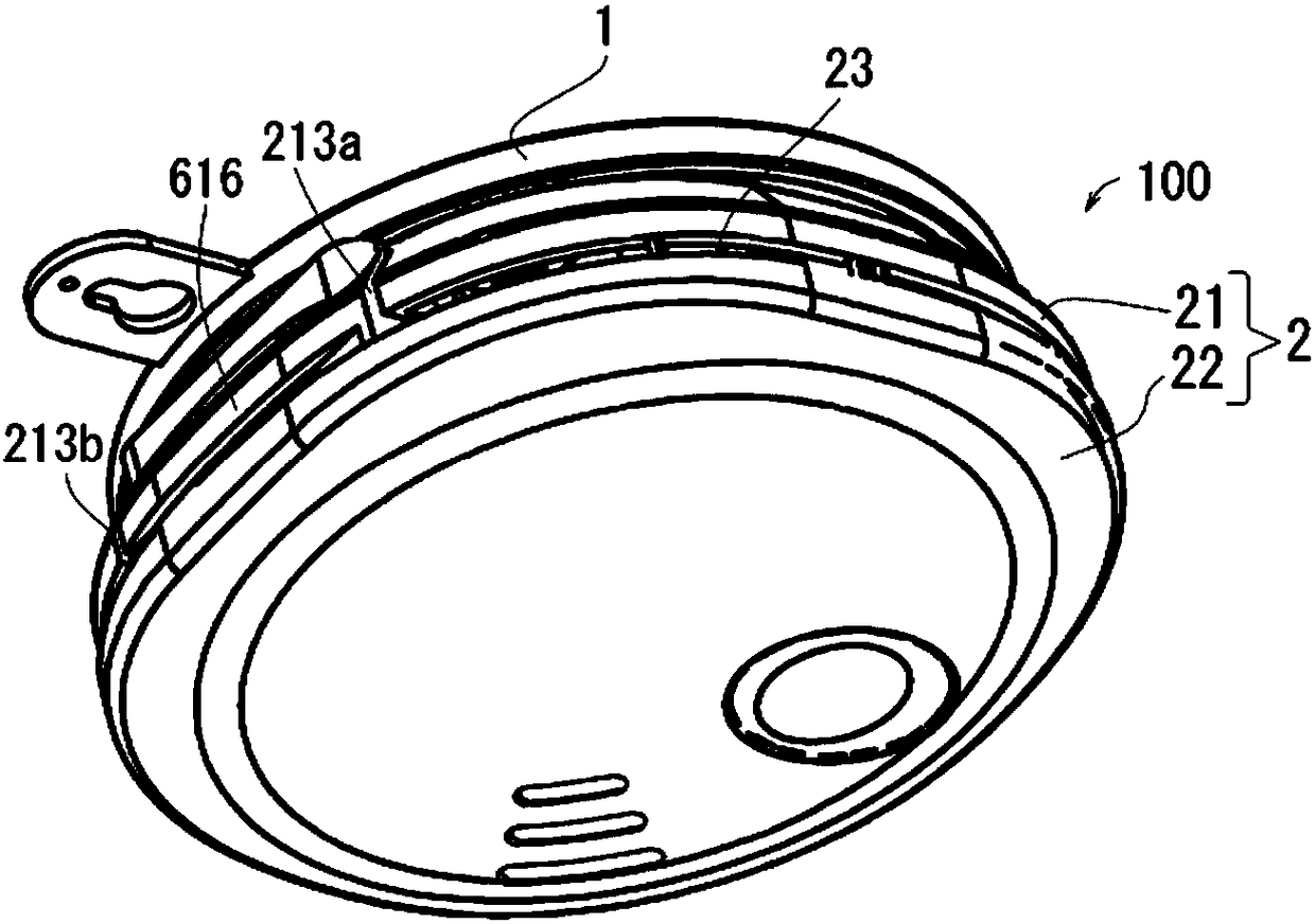
[0200] Hereinafter, an alarm device according to an embodiment of the present invention will be described in detail based on the drawings. In addition, the present invention is not limited by this embodiment.

[0201] [Basic Concept of Embodiment]

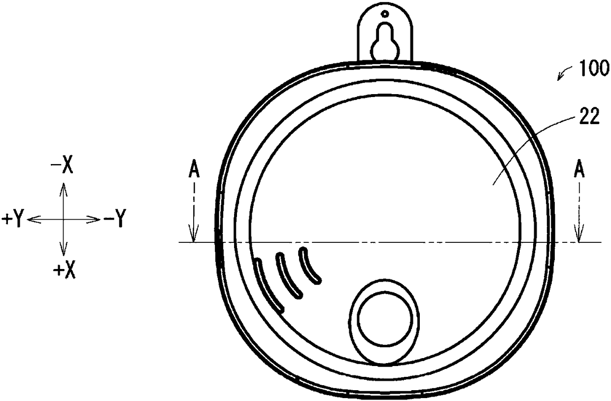
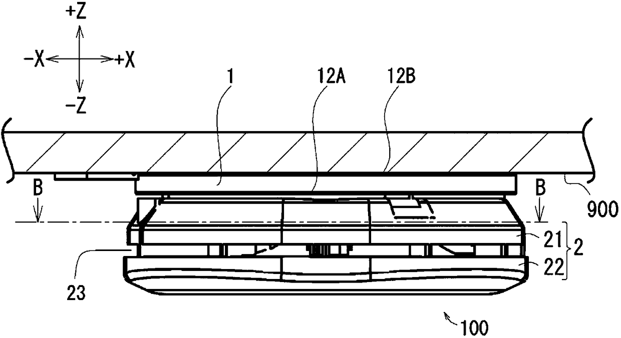
[0202] First, the basic concept of the embodiment will be described. The embodiment is roughly an alarm device installed on an installation surface of an installation object, and relates to an installation surface facing the installation surface. Here, the so-called "alarm device" is a device for alarming. Specifically, the device is used for alarming about the detected substance of the gas contained in the monitoring area, such as gas alarms and fire alarms ( smoke alarms) etc. The so-called "surveillance area" is an area to be monitored, specifically, an area where an alarm device is installed, for example, an area within a house (for example, a room, etc.), an area in a building other than a house, etc. In addition, "an obje...


PUM


Abstract

To provide an alarm device capable of promptly and reliably detecting a detection target material. Provided is an alarm device 100 which is attached to an installation surface of an installation object and has an installation surface side facing surface 12B facing an installation surface, the alarm device 100 including detection means for detecting smoke included in a gas, a casing 2 accommodatingthe detection means, and guide means for guiding a gas into the casing 2.

Description

technical field [0001] The present invention relates to an alarm device. Background technique [0002] The present invention is claimed in Japanese Patent Application No. 2015-210083 filed on October 26, 2015, Japanese Patent Application No. 2015-221522 filed on November 11, 2015, and filed on November 9, 2015 Japanese Patent Application No. 2015-219764 filed, Japanese Patent Application No. 2015-227679 filed on November 20, 2015, Japanese Patent Application No. 2015 filed on December 1, 2015 -234712, and the benefits of Japanese Patent Application No. 2015-234713 filed on December 01, 2015, are described in the specification by reference in its entirety. [0003] As is well known, existing alarms are installed under the ceiling of a surveillance area to detect smoke in the surveillance area. This alarm device includes a housing such as a circuit board for accommodating an alarm circuit; and a detection unit for detecting smoke. However, in this alarm, in order to expose ...

Claims


Application Information

Patent Timeline
Patent Type & Authority Applications(China)
IPC IPC(8): G08B17/10G08B17/00G08B17/06
CPCG08B17/107G08B17/10G08B17/113G08B17/06G08B29/043
Inventor 岛津朋彦
Owner HOCHIKI CORP
Learn More