Feeding device for shot blasting machine

A technology of feeding device and shot blasting machine, which is applied in the field of polishing or sharpening tools and grinding, which can solve the problems of shell deformation, weakening of the support force of the feed port, and the inability to automatically adjust the size of the feed channel, etc., to achieve a large support force , The structure of the device is simple and the structure is stable

Active Publication Date: 2018-08-31
重庆博创知识产权运营有限公司
View PDF7 Cites 1 Cited by
  • Summary
  • Abstract
  • Description
  • Claims
  • Application Information

AI Technical Summary

Problems solved by technology

[0005] However, the above-mentioned scheme has the following problems: 1. An upper baffle and a lower baffle are arranged at the feeding port, mainly for supporting the feeding port. The above-mentioned scheme divides the lower baffle into two. , only the fixed baffle supports the lower part of the feeding port, so the support of this part to the feeding port is weakened, and the part of the cleaning shot blasting chamber close to the feeding port is sunken toward the feeding port, resulting in serious deformation of the shell of the cleaning shot blasting chamber ; 2. When the size of the casting is larger than the feeding channel formed by the upper baffle and the lower baffle, the above scheme cannot automatically adjust the size of the feeding channel, and lacks automatic operation

Method used


Image

  • Feeding device for shot blasting machine
  • Feeding device for shot blasting machine
  • Feeding device for shot blasting machine

Examples


Embodiment Construction

[0023] The present invention will be described in further detail below by means of specific embodiments:

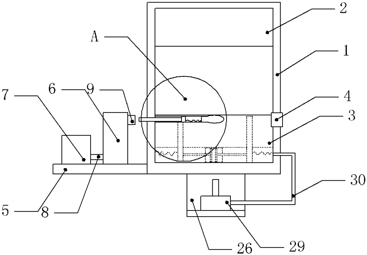
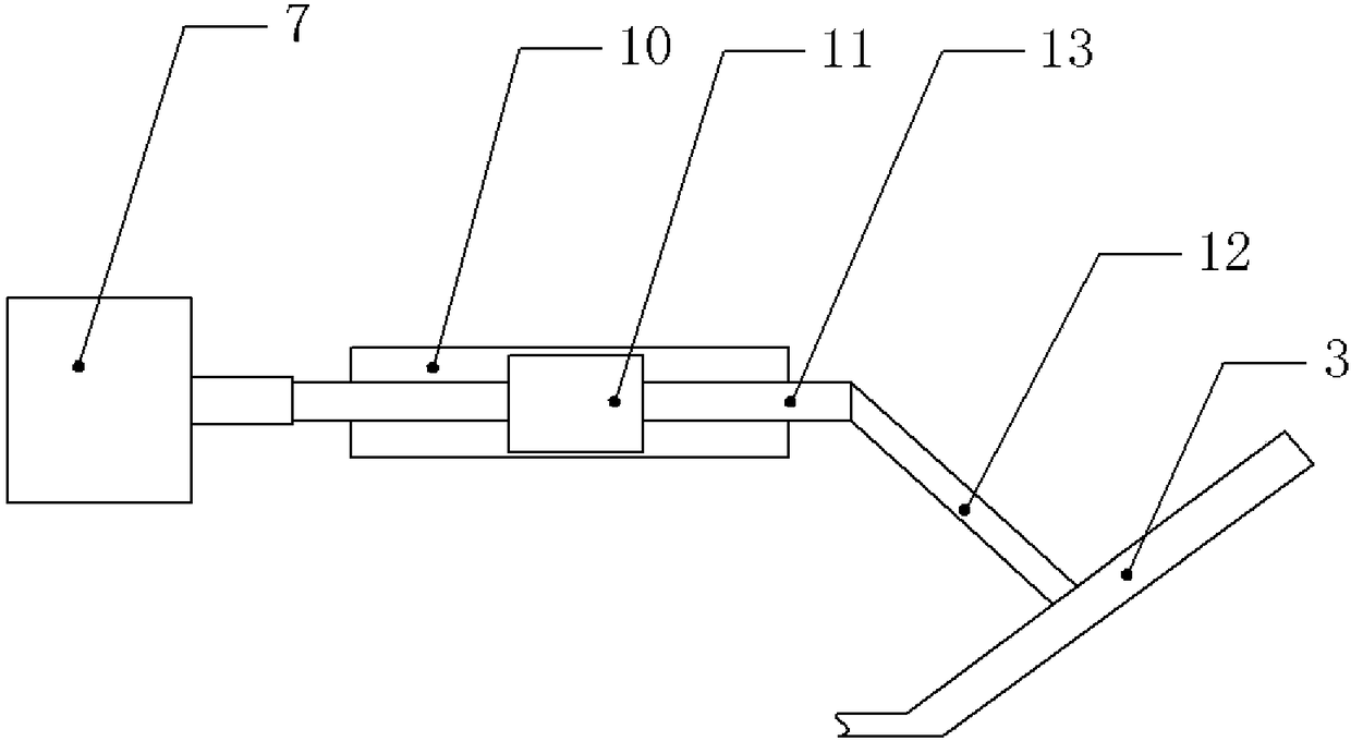
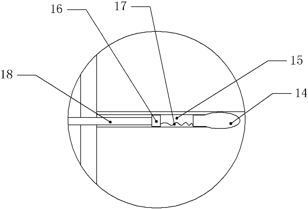
[0024]The reference signs in the accompanying drawings of the description include: feeding port 1, upper baffle plate 2, flip plate 3, card slot 4, first platform 5, air pump 6, cylinder 7, air pipe 8, switch 9, second chute 10, Second slider 11, first connecting rod 12, second connecting rod 13, air bag 14, horizontal air passage 15, third slider 16, second spring 17, control rod 18, first chute 19, adjustment box 20 , Piston 21, first cavity 22, piston rod 23, first slider 24, first spring 25, second platform 26, vertical side 27, horizontal side 28, hydraulic cylinder 29, hydraulic pipe 30.

[0025] like figure 1 Shown: The feeding device for the shot blasting machine, including the feeding port 1, the feeding port 1 is used for the shot blasting cleaning room of the shot blasting machine, the upper part of the feeding port 1 is welded with the upper baffle 2, and the...


PUM


Abstract

The invention relates to the field of tools for grinding, polishing or sharpening, and discloses a feeding device for a shot blasting machine, the feeding device comprises a feeding port, an upper baffle and a lower baffle, and the lower baffle is divided into an inverting plate from the outside to the inside. The supporting mechanism is fastened in a groove to form a whole; the outer side of thefeeding port is provided with a driving mechanism for pushing the inverting plate to be turned up and down, the supporting mechanism comprises a first sliding slot and an adjusting box, the adjustingbox is provided with two relatively-disposed pistons, a first cavity is formed between the two pistons, a piston rod is fixedly connected to one side, away from the first cavity, of each piston, the free end of the piston rod is connected with a first slider matched with a first sliding g, the top of the first slider is flushed with the top of the inverting plate, the first slider is connected tothe inner wall of the feeding port through a first spring; a second platform is arranged below the feeding port, a hydraulic cylinder is arranged on the second platform, and the hydraulic cylinder isin communication with a hydraulic pipe by the first cavity. The feeding device supports the inner wall of the feeding port to avoid depressed deformation of the casing at the feeding port.

Description

technical field [0001] The invention relates to the field of tools for grinding, polishing or sharpening, in particular to a feeding device for a shot blasting machine. Background technique [0002] In the foundry industry, most of the castings must be shot blasted. Compared with other surface treatment technologies, it is a faster, more effective, and part-reserved or stamped casting process. Generally, when castings are shot blasted, a shot blasting machine is required. Shot blasting machine is a casting equipment that uses a shot blaster to drop steel sand or steel shots at high speed and impact on the surface of the material object in order to clean or strengthen the surface of the casting. Shot blasting machines can be used to remove burrs and rust in order to maintain the gloss and integrity of the object. At the same time, the shot blasting machine can also remove surface pollutants from a partially coated surface, and provide a surface profile that increases the ad...

Claims


Application Information

Patent Timeline
Patent Type & Authority Applications(China)
IPC IPC(8): B24C9/00
CPCB24C9/00
Inventor 苏亚君
Owner 重庆博创知识产权运营有限公司
Why Eureka
Try Eureka