
Spacing ring, optical lens and camera module

An optical lens and lens module technology, applied in the field of optical lenses, can solve the problems of high release risk, affect imaging quality, and loss of lens height, and achieve good imaging effect, good assembly stability, and improved imaging quality and effect. Effect

Pending Publication Date: 2018-08-28
ZHEJIANG SUNNY OPTICAL CO LTD
View PDF0 Cites 3 Cited by
  • Summary
  • Abstract
  • Description
  • Claims
  • Application Information

AI Technical Summary

Problems solved by technology

Traditional imaging lenses generally do not have space to use a supporting member (spacer ring), and can only be directly supported by two lenses. However, such a direct bearing makes the lens lose its height, and the risk of separation is high, and there is a stress concentration on the assembled lens, which affects Image quality

Method used


Image

  • Spacing ring, optical lens and camera module
  • Spacing ring, optical lens and camera module

Examples


Embodiment Construction

[0027] In order to more clearly describe the embodiments of the present invention or the technical solutions in the prior art, the following will briefly introduce the drawings that are used in the embodiments. Apparently, the drawings in the following description are only some embodiments of the present invention, and those skilled in the art can also obtain other drawings according to these drawings without creative efforts.

[0028] When describing the embodiments of the present invention, the terms "vertical", "transverse", "upper", "lower", "front", "rear", "left", "right", "vertical", " The orientation or positional relationship expressed by "horizontal", "top", "bottom", "inner" and "outer" is based on the orientation or positional relationship shown in the relevant drawings, which are only for the convenience of describing the present invention and simplifying the description, and It is not to indicate or imply that the device or element referred to must have a particu...


PUM


Abstract

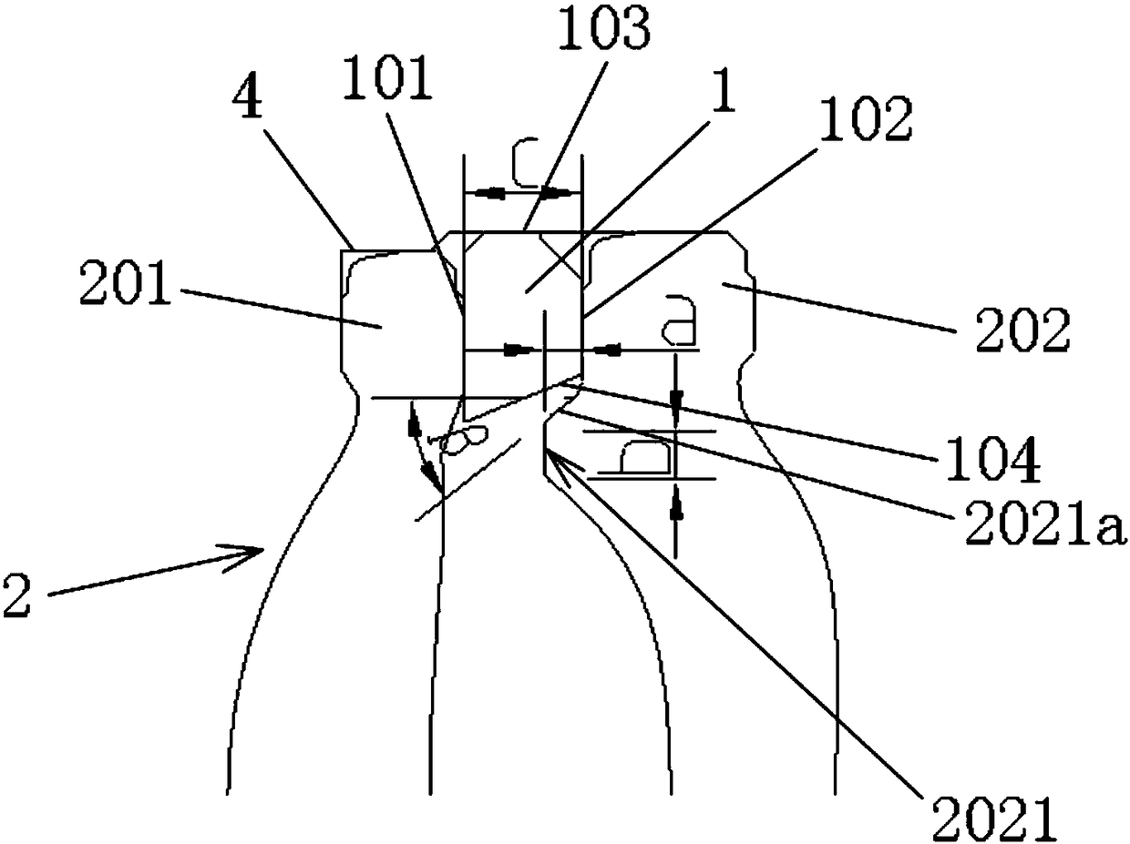
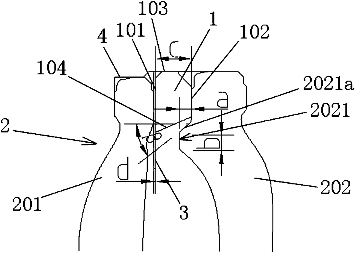
The invention relates to a spacing ring (1), an optical lens and a camera module. The spacing ring (1) is arranged in a lens cone of the camera module, and is used for spacing two adjacent lenses in the optical lens; the spacing ring (1) comprises a first surface (101) abutting against one of the lenses, a second surface (102) abutting against the other lens, as well as a third surface (103) connected with the inner wall of the lens cone; and the spacing ring (1) also comprises a fourth surface (104) which is far away from the third surface (103) and is used for avoiding the lenses in the optical lens. When the optical lens is assembled according to the spacing ring, the lenses can be avoided, each lens in the optical lens is provided with a boss, can provide a mounting space for the spacing ring and can avoid the spacing ring. Therefore, after the optical lens or the camera module is assembled, the stability is higher, the imaging quality is guaranteed, and the problem that the lens stress is concentrated is solved.

Description

technical field [0001] The invention relates to the field of optical lenses, in particular to a spacer ring, an optical lens comprising the spacer ring and a camera module comprising the optical lens. Background technique [0002] In recent years, with the continuous advancement of science and technology, the popularization of personal electronic products and mobile communication products equipped with imaging devices such as mobile phones and tablet computers has led to the rise of miniaturized imaging lenses. Miniaturized imaging lenses with excellent imaging quality demand has also increased significantly. Traditional imaging lenses generally do not have space to use a supporting member (spacer ring), and can only be directly supported by two lenses. However, such a direct bearing makes the lens lose its height, and the risk of separation is high, and there is a stress concentration on the assembled lens, which affects Image quality. Contents of the invention [0003]...

Claims


Application Information

Patent Timeline
Patent Type & Authority Applications(China)
IPC IPC(8): G02B7/02G02B27/00G03B30/00
CPCG02B7/021G02B7/026G02B27/0018
Inventor 丁先翠朱林波
Owner ZHEJIANG SUNNY OPTICAL CO LTD
Learn More