Truss bridge system for truss-rope composite structure

A composite structure and truss bridge technology, applied in the field of truss bridge system, can solve the problems of prolonged construction period, insufficient torsional rigidity, and ignoring the influence of load factors such as eccentric force, and achieve the reduction of vertical deflection and lateral deflection , The torsion resistance of the bridge body is improved, and the effect of improving the comfort of pedestrians

Pending Publication Date: 2018-08-28
SOUTH CHINA UNIV OF TECH
View PDF0 Cites 0 Cited by
  • Summary
  • Abstract
  • Description
  • Claims
  • Application Information

AI Technical Summary

Problems solved by technology

[0003] 1. The height of the steel box girder pedestrian bridge is relatively high, and the stairways on both sides are too long;
[0004] 2. The price of aluminum alloy materials is high, and the elastic modulus is only one-third of that of steel, so its wide application is limited;
[0005] 3. Uncertainty brought about by pouring on site construction, extension of construction period and construction waste
[0007] 1. On-site construction is complicated;
[0008] 2. The structural stability of the connection cannot be guaranteed;
[0009] 3. Does not consider the influence of load factors such as eccentric force caused by installation and placement errors
[0011] 1. The lateral rigidity is insufficient, and lateral loads such as human thrust on the handrail and wind load will appear in actual use, which will affect the use effect of the truss bridge;
[0012] 2. Insufficient torsional rigidity, when the structure is disturbed, it is easy to cause the instability of the rod

Method used


Image

  • Truss bridge system for truss-rope composite structure
  • Truss bridge system for truss-rope composite structure
  • Truss bridge system for truss-rope composite structure

Examples


Embodiment Construction

[0040] The present invention will be described in detail below with reference to the accompanying drawings and specific implementation methods, and the embodiments will not be repeated here one by one, but the applicability of the present invention is not limited to the following embodiments.

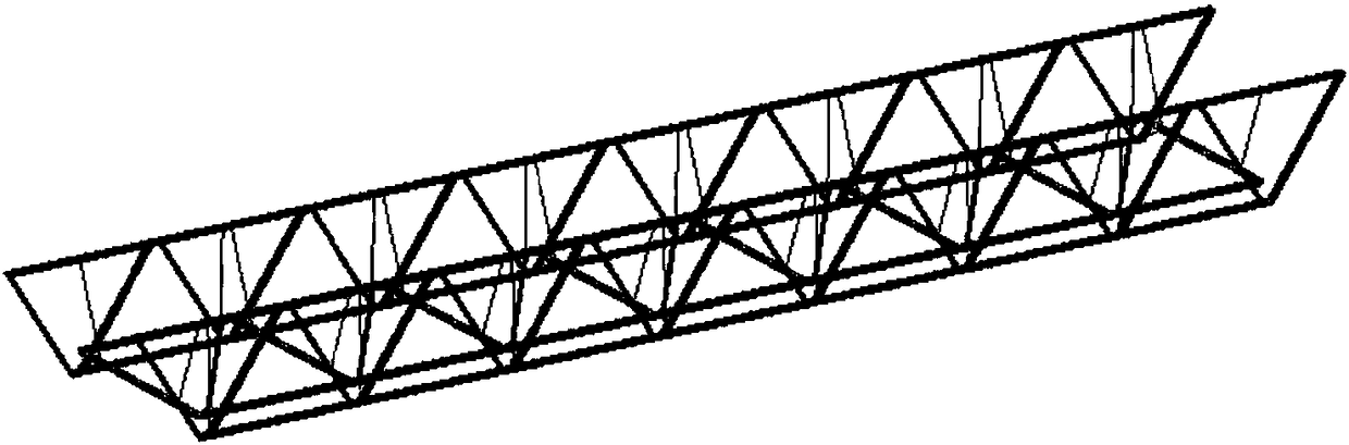
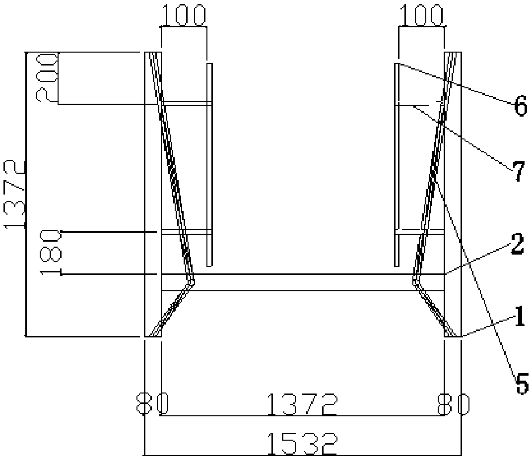
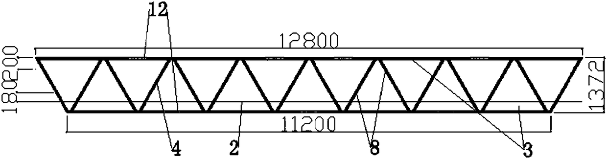
[0041] Such as figure 1 , figure 2 As shown, a truss bridge system of a truss-cable composite structure, including a light steel bridge skeleton, supports the support arranged at the bottom of the light steel bridge skeleton through several bottom connectors 15, and the light steel bridge skeleton includes Q235 A light steel handrail truss 1 and a light steel walkway truss 2 assembled with cold-formed thin-walled steel. The light steel handrail truss 1 is symmetrically fixed on both sides of the light steel walkway truss 2 . 1. A number of steel cables 5 are evenly spaced along the length direction between the lower chords. The reserved holes corresponding to the web members 4 of the...


PUM


Abstract

The invention discloses a truss bridge system for a truss-rope composite structure. The truss bridge system comprises a light steel bridge skeleton and a supporting seat which is arranged at the bottom of the light steel bridge skeleton through the support of a plurality of bottom connecting pieces, wherein the light steel bridge skeleton comprises a light steel handrail truss and a light steel footpath truss which are assembled by cold-formed thin-walled light steel, the light steel handrail truss is symmetrically fixed on two sides of the light steel footpath truss, a plurality of steel ropes are uniformly and alternately arranged between the upper chord and lower chord of the light steel handrail truss along a length direction, two ends of each steel rope are respectively fixed on the upper chord and lower chord of the light steel handrail truss, the middle parts of the steel ropes pass through the preformed holes of a corresponding web member of the light steel footpath truss, andthe middle parts of the steel ropes and the preformed holes are oppositely fixed. The truss bridge system is high in stability, more compact and reliable in structure as a whole, more convenient and simpler in maintenance, safe in construction and good in economical efficiency.

Description

technical field [0001] The invention belongs to the technical field of buildings and relates to a truss bridge system with a truss-cable composite structure. Background technique [0002] Steel structure bridges are widely used in the field of footbridges in my country, and the development trend of modern footbridges is to develop towards new structures, new materials, and new technologies, and to become factors that shape urban landscapes. Traditional steel structure bridges mainly have the following aspects point question: [0003] 1. The height of the steel box girder pedestrian bridge is relatively high, and the stairways on both sides are too long; [0004] 2. The price of aluminum alloy materials is high, and the elastic modulus is only one-third of that of steel, so its wide application is limited; [0005] 3. Uncertainty brought about by on-site pouring construction, extension of construction period and construction waste. [0006] At present, light steel structure...

Claims


Application Information

Patent Timeline
IPC IPC(8): E01D6/00
CPCE01D6/00
Inventor 许竞李静李泽玉杨轩张仰镛刘俊豪黄麟倚
Owner SOUTH CHINA UNIV OF TECH
Why Eureka
Try Eureka