
Motor bearing polishing machine

A technology for motor bearings and polishing machines, which is applied in the direction of surface polishing machine tools, grinding/polishing equipment, grinding/polishing safety devices, etc., which can solve the problems of bearing accuracy and quality not being guaranteed, labor intensity, instability, etc. question

Pending Publication Date: 2018-08-24
SUZHOU INST OF INDAL TECH
View PDF7 Cites 5 Cited by
  • Summary
  • Abstract
  • Description
  • Claims
  • Application Information

AI Technical Summary

Problems solved by technology

[0003] At present, the conventional polishing method is to manually polish the outer circular surface, conical surface, short inner circular surface and long outer circular surface of the motor bearing, which not only has low polishing efficiency, but also requires manual labor. At the same time, due to the instability of manual polishing, the accuracy and quality of bearings after manual polishing are often not guaranteed

Method used


Image

  • Motor bearing polishing machine
  • Motor bearing polishing machine
  • Motor bearing polishing machine

Examples


Embodiment Construction

[0047] The present invention will be described in detail below with reference to the accompanying drawings and in combination with embodiments.

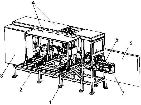
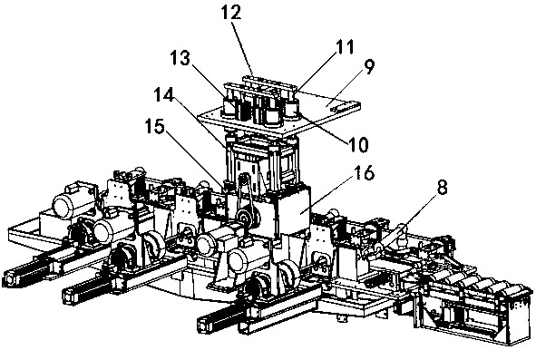
[0048] see figure 2 , Figure 11 and Figure 12 As shown, a motor bearing polishing machine includes a frame 2, and the frame 2 is sequentially provided with a feeding mechanism, a conical surface polishing mechanism, a long inner circular surface rough polishing mechanism, and an outer circular surface polishing mechanism from right to left. Mechanism, long inner circular surface fine polishing mechanism, short inner circular surface polishing mechanism and finished product collection box 34; described feeding mechanism, described conical surface polishing mechanism, described long inner circular surface rough polishing mechanism, described outer circular surface An industrial manipulator 8 for transferring the bearing 6 to be processed is respectively arranged on the rear left side of the polishing mechanism, the long inner surf...


PUM


Abstract

The invention discloses a motor bearing polishing machine. The motor bearing polishing machine comprises seven stations of a material inlet mechanism, a circular conical surface polishing mechanism, along inner circular surface rough polishing mechanism, an outer circular surface polishing mechanism, a long inner circular surface fine polishing mechanism, a short inner circular surface polishingmechanism and a finished product collecting box which are arranged on a rack, industrial mechanical arms are arranged at positions between the seven stations correspondingly, wherein the right rears of the circular conical surface polishing mechanism, the long inner circular surface rough polishing mechanism, the long inner circular surface fine polishing mechanism and the short inner circular surface polishing mechanism are provided with clamping mechanisms correspondingly, and upper compressing mechanisms are arranged above the long inner circular surface rough polishing mechanism, the longinner circular surface fine polishing mechanism and the short inner circular surface polishing mechanism correspondingly. By means of the motor bearing polishing machine, full-automatic control is realized, seven working procedures of material inlet, circular conical surface polishing, long inner circular surface rough polishing, outer circular surface polishing, long inner circular surface fine polishing, short inner circular surface polishing and finished product collecting of motor bearings to be polished can be finished at a time, the polishing efficiency and precision are high, the quality is good, furthermore, the cost is low, and the labour strength is greatly lowered.

Description

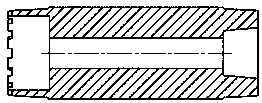
technical field [0001] The invention belongs to the field of automatic special processing equipment, in particular to a motor bearing polishing machine controlled by PLC, which is used for automatic polishing of motor bearings. Background technique [0002] Common motor bearings to be polished such as figure 1 As shown, the outside of the bearing in the figure is an outer circle, the left end of the bearing is a short inner circle, the right end of the bearing is a conical surface, and the inside of the bearing is a long inner circle. For motor bearings to be able to be used normally, the outer circular surface, conical surface, short inner circular surface and long outer circular surface must be polished working surfaces. Among them, the long inner circular surface has the highest requirement and needs to be divided into rough polishing and fine polishing. Two processes. [0003] At present, the conventional polishing method is to manually polish the outer circular surfac...

Claims


Application Information

Patent Timeline
IPC IPC(8): B24B5/14B24B5/35B24B27/00B24B5/04B24B41/06B24B29/04B24B55/06B24B41/02
CPCB24B5/04B24B5/14B24B5/355B24B27/0076B24B29/04B24B41/02B24B41/067B24B55/06
Inventor 李春雷王润民石皋莲顾涛
Owner SUZHOU INST OF INDAL TECH
Learn More